hi,
I hope you are all well,
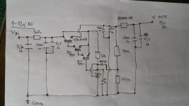
I bought this low noise PSU from China and made schematics for it,
could you please have a look at it or check if the design makes sense?, quite often China boards are criticized.
any suggestion to improve it?
best
KR.
....there is a mistake in this schematics!,...sorry my mistake,...please look at post *12 with an updated and corrected version.
I hope you are all well,
I bought this low noise PSU from China and made schematics for it,
could you please have a look at it or check if the design makes sense?, quite often China boards are criticized.
any suggestion to improve it?
best
KR.
....there is a mistake in this schematics!,...sorry my mistake,...please look at post *12 with an updated and corrected version.
Attachments
Last edited:
If its a TL431 that's being used as the Vref then the claimed 'low noise' isn't very. Your average TL431 runs around 100nV/rtHz (they do vary quite a lot, Chinese made ones are likely worse than that).
Yes it isn't that "noiseless " , looking at the graph it shoots up at the low frequencies typical of a mains powered power supply reaching 220 nV at 10Hz.
The 100pF does not go in series with midpoint of the resistive voltage divider and to the TL431 control pin.
...any new ideas to fix the problem? 🙂If its a TL431 that's being used as the Vref then the claimed 'low noise' isn't very. Your average TL431 runs around 100nV/rtHz (they do vary quite a lot, Chinese made ones are likely worse than that).
The 100pF does not go in series with midpoint of the resistive voltage divider and to the TL431 control pin.
hi,
I have looked at the schematics of tl431 and I was wondering about this 100pk capacitor as well,...would you like to post any improved schematics to this supply?
thank you for taking part in this thread.
fantastic news!, i didn't expect any better, that's why I'm in here with this supply.If its a TL431 that's being used as the Vref then the claimed 'low noise' isn't very. Your average TL431 runs around 100nV/rtHz (they do vary quite a lot, Chinese made ones are likely worse than that).
perhaps there is a potential to it, but it has to be done properly.
what do you mean by saying I swapped the emitters and collectors?You have most likely swapped the emitters and collectors for the BC550 transistors.
hi,The 100pF does not go in series with midpoint of the resistive voltage divider and to the TL431 control pin.
well spotted, I just updated the (corrected schematics)
my mistake, sorry.
thanx.
Attachments
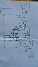
I believe that if you draw the 100pF capacitor going from the midpoint of the two 10K resistors and to ground with the feedback going to the TL431 control pin (without connection to the TL431 cathode), AND swap emitters and collectors of the BC550 transistors you are very close to a functional circuit.
Could also be that the 100pF is intended to provide local feedback as shown in your last schematic.
Your BC550 still seem wrong.
Your BC550 still seem wrong.
And you should remote the 10uF cap across the TL431, it is not a zener that should be filtered but a real closed loop regulator. The voltage reference is inside the TL431 a thus can’t be filtered.
hi,Could also be that the 100pF is intended to provide local feedback as shown in your last schematic.
Your BC550 still seem wrong.
would you mind drawing simple schematics so we can see what you mean?
..same here, a little update sketch of correct operation?And you should remote the 10uF cap across the TL431, it is not a zener that should be filtered but a real closed loop regulator. The voltage reference is inside the TL431 a thus can’t be filtered.
Could also be that the 100pF is intended to provide local feedback as shown in your last schematic.
Your BC550 still seem wrong.
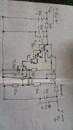
please have a look at my change,...would that work as it should?
Attachments
I`m sorry. No schematic program on this laptop. I will have to explain in words.
The 10uF seems right. I use it myself in my TL431 regulators. It is recommended in the TL431 datasheet if the TL431 has more than a minimum of capacitive loading. Figure 16 of the TI datasheet.
Darlington transistor - Wikipedia describes the ordinary (two transistor) NPN Darlington coupling. Your add another NPN transistor to the upper NPN transistor and you have the triple NPN Darlington coupling. That is what is used in your circuit.
- Home
- Amplifiers
- Power Supplies
- ultra low noise psu from China