

Hi Marc,
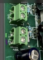
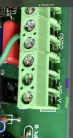
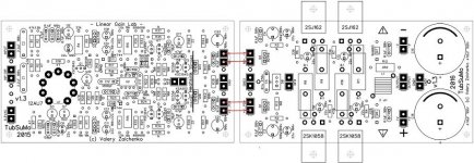
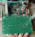
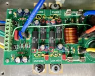
It looks like Terry is right - the silkscreen markings may be swapped om the negative side of the IPS board. The boards were designed to be connected as shown in the image attached.
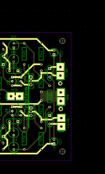
Can you please drop a photo of the bottom side of IPS board.
Let's see the traces.
Cheers,
Valery
It looks like Terry is right - the silkscreen markings may be swapped om the negative side of the IPS board. The boards were designed to be connected as shown in the image attached.
Can you please drop a photo of the bottom side of IPS board.
Let's see the traces.
Cheers,
Valery
Attachments
I see. If the IPS -V is intended to connect to the two GND points at that end of the board, then the top silkscreen label is incorrect t for -V and -ND. Please confirm.
Thanks for your input!
Thanks for your input!
Attachments

Thank you all for your help! Especially Eagle Eye Terry!
Lol, Happy to help.
Sorry I didn’t note the discrepancy. It’s been some time since I took those boards out of operation.
It looks like your close to trying them out
It looks like your close to trying them out
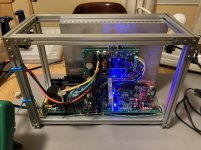
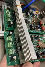
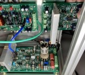
First the good news: it works and sounds very good on my little test speaker!
The rest of the news: it had a terrible hum on the output at first, with no audio input connected. Shorted audio input reduced the hum quite a bit. DC offset would vary quite a bit from -20mV to +20mV even after warming up. So I removed the speaker protection board from the output. Similar hum. Then I changed to powering the tube (still 6.3vdc) with a separate wall wart smps instead of the larger smps auxiliary output. Hum diminished, but still there. DC offset much more stable at a few mV. As long as there is audio input or that input is shorted, the hum is relatively quiet.
I am very encouraged by what I can hear, but have more work to do. Still need to reason out the exact biasing procedure. I know these were set by Evan previously and so I tested music playback as-is. I could use a little help as a novice on what needs to be done setting the IPS trim pot and the OPS trim pot. Do I need dummy output loads?
Last edited:
Ill need to read through the thread to remember the setting procedure. The trim pot on the output board sets the bias current. You figure the current by measuring voltage across a pair of emitter resistors. I can’t remember the desired value.
The op amp should hold the offset close to zero.
I ran the heaters from 6.3VAC.
Hum is most certainly a grounding issue.
The op amp should hold the offset close to zero.
I ran the heaters from 6.3VAC.
Hum is most certainly a grounding issue.
Copied from earlier in the thread:
Ah! Right, good point
The best performance is observed at 80-100mA per pair. Having source resistors 0.1R each and measuring at two of them in series (0.2R), this equals to 16-20mV.
My test heatsink is a bit smallish, so I keep it at the lower end (16mV -> 80mA).
Note, how smoothly the bias adjusts and how stable it sits once it's set to certain value - lateral FETs rock
- Home
- Amplifiers
- Solid State
- Ultra-high performance, yet rather simple - hybrid and more!