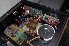
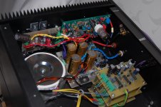
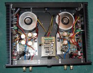
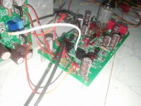
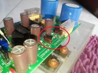
Here are some pictures from my construction.
Some notes:
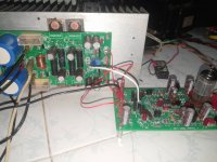
a. I was looking for about 100W per channel. Capacitance reservoir is CRC style, there are 2 x 6800uF capacitos per channel.
b. The box is used for the third time now - the previous amps did not satisfy my preferences. So you could find some holes that are not used this time.
c. Soft start is also from older project. It is based on CMOS counter that counts pulses from power supply and then switch on relay.
d. DC protection I already described in my previous post.
This is the first time when I used tube 😉 . Used tubes are made by JJ electronic producer.
Have fun,
Ladislav
Some notes:
a. I was looking for about 100W per channel. Capacitance reservoir is CRC style, there are 2 x 6800uF capacitos per channel.
b. The box is used for the third time now - the previous amps did not satisfy my preferences. So you could find some holes that are not used this time.
c. Soft start is also from older project. It is based on CMOS counter that counts pulses from power supply and then switch on relay.
d. DC protection I already described in my previous post.
This is the first time when I used tube 😉 . Used tubes are made by JJ electronic producer.
Have fun,
Ladislav
Attachments

Here are some pictures from my construction.
Some notes:
a. I was looking for about 100W per channel. Capacitance reservoir is CRC style, there are 2 x 6800uF capacitos per channel.
b. The box is used for the third time now - the previous amps did not satisfy my preferences. So you could find some holes that are not used this time.
c. Soft start is also from older project. It is based on CMOS counter that counts pulses from power supply and then switch on relay.
d. DC protection I already described in my previous post.
This is the first time when I used tube 😉 . Used tubes are made by JJ electronic producer.
Have fun,
Ladislav
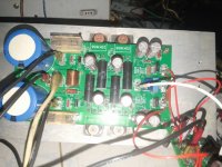
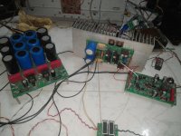
2 x transformers, 2 x PSU boards - I like the approach

I'm running a 55vdc rails voltage and the noise in the speaker seems to be that it lacks ground
I did the right thing and please help with this noise
thank you
I did the right thing and please help with this noise
thank you
Attachments
-
 22893945_1469088363207246_5737948127180889403_n.jpg94.1 KB · Views: 212
 -
 22853343_1469088503207232_2784114480698218698_n.jpg77.3 KB · Views: 222
 -
 22853060_1469088303207252_276734542614086339_n.jpg87.8 KB · Views: 300
 -
 22815117_1469088563207226_5102369900743063573_n.jpg91.3 KB · Views: 686
 -
 22815271_1469089203207162_71789983312931166_n.jpg89.3 KB · Views: 229
I'm running a 55vdc rails voltage and the noise in the speaker seems to be that it lacks ground
I did the right thing and please help with this noise
thank you
Hi,
Normally, if the amplifier is wired properly, it is very quiet at idle.
First thing I would recommend - put 2 x 0.1uF capacitors between both tube filament connection wires and the main PSU ground.
Also, revise your grounding scheme - see a good article on amplifier wiring here:
GROUND LOOPS: HOW TO WIRE-UP AN AUDIO AMPLIFIER FOR ZERO HUM AND NOISE
Let us know how it goes 😉
Cheers,
Valery
I have finished editing the noise.Hi,
Normally, if the amplifier is wired properly, it is very quiet at idle.
First thing I would recommend - put 2 x 0.1uF capacitors between both tube filament connection wires and the main PSU ground.
Also, revise your grounding scheme - see a good article on amplifier wiring here:
GROUND LOOPS: HOW TO WIRE-UP AN AUDIO AMPLIFIER FOR ZERO HUM AND NOISE
Let us know how it goes 😉
Cheers,
Valery
I play music to small volume sounds very good,I opened louder the sound seemed to be broken sound at the speaker
I have finished editing the noise.
I play music to small volume sounds very good,I opened louder the sound seemed to be broken sound at the speaker
Something is not right. It should produce quality sound almost up to clipping.
Can you please show the sine waves (1KHz, 10KHz) at some high swing?
One more question - what is your rails voltage?
If the capacitor is attached to it it will not suffer.Something is not right. It should produce quality sound almost up to clipping.
Can you please show the sine waves (1KHz, 10KHz) at some high swing?
One more question - what is your rails voltage?
I ran the 55vdc rails.
Attachments
Did you look at the sine / square waves with an oscilloscope at different output swings?
Do you see some ringing / oscillation at the output?
It would be good if you would publish the schematics of both IPS and OPS modules exactly "as built" - I would be able to give some recommendations then.
Do you see some ringing / oscillation at the output?
It would be good if you would publish the schematics of both IPS and OPS modules exactly "as built" - I would be able to give some recommendations then.
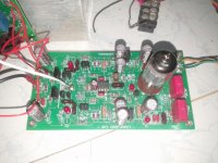
One thing right away - I recommend to use 2 x red LEDs in VAS cascodes - I see only one LED in each shoulder on your photos. This may be one of the reasons of higher distortion at higher volumes.
Are they to replace the blue LEDs in the post1 schematics?One thing right away - I recommend to use 2 x red LEDs in VAS cascodes - I see only one LED in each shoulder on your photos. This may be one of the reasons of higher distortion at higher volumes.
That's right - later on, I have replaced those single blue LEDs by 2 x red LEDs.
I have tested configuration with single red LEDs, but it showed poorer performance at high swings with some types of LEDs, so I don't recommend using it.
I have tested configuration with single red LEDs, but it showed poorer performance at high swings with some types of LEDs, so I don't recommend using it.
could you add a link to post1 for the updated schematic?
see this example of a post1 index
2stageEF high performance class AB power amp / 200W8R / 400W4R
see this example of a post1 index
2stageEF high performance class AB power amp / 200W8R / 400W4R
I use 2 red LEDs in VAS cascodesOne thing right away - I recommend to use 2 x red LEDs in VAS cascodes - I see only one LED in each shoulder on your photos. This may be one of the reasons of higher distortion at higher volumes.
I am running a 1 LED test.
I removed the two 220pf OP capacitors and it immediately deformed the sound
Nice Amp.
Always wanted to build a tube hybrid amp.
Any link to final version of this IPs and OPS board.
I have a few pairs of MJL 21193 / 94 and 2sc2922 / 1216 and 2sk1530. trying to put them to good use. I might also have ECC88 tube- will have to search for it though.
Always wanted to build a tube hybrid amp.
Any link to final version of this IPs and OPS board.
I have a few pairs of MJL 21193 / 94 and 2sc2922 / 1216 and 2sk1530. trying to put them to good use. I might also have ECC88 tube- will have to search for it though.
I think the latest schematics are here. Ultra-high performance, yet rather simple - hybrid and more! The TubSuMo output board is designed to use lateral mosfet output devices, but the TubSuMo input pairs very well with the NS Output board. Revisiting some "old" ideas from 1970's - IPS, OPS. That output board can use 2SC2922 / 2SA1216 . You'll have problems finding a modern high power amplifer design that will work reliably with your MJL 21193 / 94 devices. They are too slow and will suffer from shoot through or cross conduction and self destruct with most EF3 designs.
Last edited:
I think the latest schematics are here. Ultra-high performance, yet rather simple - hybrid and more! The TubSuMo output board is designed to use lateral mosfet output devices, but the TubSuMo input pairs very well with the NS Output board. Revisiting some "old" ideas from 1970's - IPS, OPS. That output board can use 2SC2922 / 2SA1216 . You'll have problems finding a modern high power amplifer design that will work reliably with your MJL 21193 / 94 devices. They are too slow and will suffer from shoot through or cross conduction and self destruct with most EF3 designs.
Ok I can get more of 2sc2922 / 2sa1216 as needed.
Can you guide me to pcb layout for the same.
Also in one of the threads a image was posted for speaker protect.
Thanks
Vikram
I don't think Valery ever posted Gerber files or layouts for any of these boards. We have boards available through our website (I have original version boards and updated SMT versions in stock) or you can PM Valery and see if he will send you some files.
Right - in general, there are 2 versions of the amplifier:
1) Through-hole version, utilizing 2 pairs of 2sk1058/j162 lateral FETs per channel;
2) SMD version, utilizing NS Modular OPS carrier board with 3 pairs of 2sc2922/a1216 per channel.
Option 2 is significantly more expensive because of the OPS cost.
ECC88 will not work properly here - the front-end is particularly designed for 12AU7/ECC82 tube.
Cheers,
Valery
Is there any way of getting pcb diagram in any format, jpeg or pdf. i am really wanting to build this amp. Ips and smd version Ns ops board.
- Home
- Amplifiers
- Solid State
- Ultra-high performance, yet rather simple - hybrid and more!