Most modern output devices will work fine, but they won't have as good SOA. If you don't plan to push 150+ watts out it's not really an issue though.
To be honest I have no clue if I will need 150+ watts... Why? I built a pair of great sounding (and looking 😀) speakers, but some 80 dB/W/m and 4 ohms impedance require a bunch of watts at the input for a "yes, have fun!" listening level. Currently I drive them with my Yamaha AVR, but it runs out of steam, loses control of the LF driver coils and turns bass punches into some flubber...
150 watts should be fine - if they're delivered with control and current reserves. I had a quick look on the 6 op device version of NS OPS, but hey... it's still just a living room 😉
Prost!
Holgi
150 watts should be fine - if they're delivered with control and current reserves. I had a quick look on the 6 op device version of NS OPS, but hey... it's still just a living room 😉
Prost!
Holgi
I played with my dormant TubSuMo project today.
Good news is I fixed the grounding scheme and eliminated mains hum.
Bad news is I have a weird situation with the IPS, I think. The DC offset servo doesn’t seem to be working. DC offset settles at -4.3V. Plus there is some audible non-mains noise at the output. I tried a couple different sources and the issue seems to be with the amp. Low level static-like sound that gets louder when there is music playing.
What points on the boards should I measure for accurate voltages?
I know the SMPS was delivering +/-60VDC and the tubes were getting 6.3VDC (separate wall wart supply). I switched tubes and the problem persisted. The bias for the outputs was 20mV.
What you're describing actually sounds like a bad ground. What voltage is the servo putting out on pin 6?
Pin 6 of U2 ( the LF411) is the output of the servo. It might be easier to measure at the input side of R17 or R18 (they're all connected).
Thank you. Across R18 is 3.06V. I may not understand what you mean by the input side.
One side of R18 to input GND is 2.5V.
The other side is 5.47V.
I apologize for being a little slow. I greatly appreciate your help.
One side of R18 to input GND is 2.5V.
The other side is 5.47V.
I apologize for being a little slow. I greatly appreciate your help.
Last edited:
It looks like the servo isn't trying to adjust too much. It should be trying to go to one rail or the other with that much offset. This really looking like a grounding issue.
Last edited:
Can you measure the voltage between input ground and the power supply ground ( right at the supply)?
I edited my previous post as you replied.
Also, R18 to psu GND is -1.85 on the side closest to the opamp ic, and 0.76V on the other side.
Also, R18 to psu GND is -1.85 on the side closest to the opamp ic, and 0.76V on the other side.
You have no ground reference. Either the supply ground isn't connected to the input board or you blew a ground trace off somewhere.
Are you connecting the input board ground through the output board? If so did you install the ground jumper on the output board?
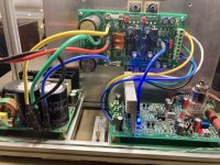
Picture attached.
To review, I purchased these boards from Evan. They worked without problems for him. So I know I have caused whatever issue I’m having now. His OPS boards had a GND wire across the board from one side to the other. I removed that, based on recommendations from you and Valery before. I also made sure the speaker GND is directly connected to psu gnd.
I measure 0R from psu GND to the GND points connecting OPS and IPS, as well as the input GND on the IPS.
I measure 0.7R from PSU GND to GND1 on the OPS, as well as to speaker output jack. Does that mean something is wrong with the PSU - OPS GND?
Attachments
Run the ground from the input stage straight to the power supply ground. That's the quietest way to connect it.
- Home
- Amplifiers
- Solid State
- Ultra-high performance, yet rather simple - hybrid and more!