Maximum voltage swing is 25V peak-to-peak, that as +12,5V and -12,5V.same calculus for inner ring of current mirror bjts - Q5,6,7,8 - same Iq as previous , figure out CE voltages for dissipation calculus
The core is the SuSy, the rest is interpretation just like the paralleled version which N.Pass liked. (see attachment)
I have no clue on the differences in sound, but no matter, it will be the best I've ever owned 🙂
Attachments

try harder ..... when dealing with technical things , being precise is beneficial .....
so , define CE voltage for each bjt , write it down , do dissipation calc - both static and peak
you don't need doing that for me ......

so , define CE voltage for each bjt , write it down , do dissipation calc - both static and peak
you don't need doing that for me ......
I will need to go over all the notes and do sim. Remember, I have no idea what I'm doing, I'm a n00b, so steep learning curve here. 🙂
The BC850/860 has a Pd of 310mW which I am sure is more than adequate. The [hfe] target is a different story. I know the recommendation is more than 100, but HOW much more.
The BC850/860 has a Pd of 310mW which I am sure is more than adequate. The [hfe] target is a different story. I know the recommendation is more than 100, but HOW much more.
But ideally you want the FETs to be matched, it is a mantra repeated over and over when you read about these things. Hfe on the other hand, well... I will investigate it a bit further. I just wana make sure that everything is done properly. If that mean 1% or 13% or whatever, that I don't know. But it can't harm to match
Two places that sell the SOT-23 version. Both of them can deliver the LSJ74B if you send them an email.
US; LSK170B SOT-23 3L | Linear Integrated Systems | Trendsetter Electronics
Europe: Micross Components Ecommerce System
Oneminde
US; LSK170B SOT-23 3L | Linear Integrated Systems | Trendsetter Electronics
Europe: Micross Components Ecommerce System
Oneminde


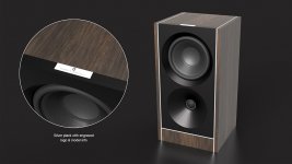
One of the reasons I am doing this project - besides the volume wheel 😀 - is my passion for loudspeakers. That too has been a long journey but I am finally ready to start prototyping soon. So when the need for a really nice stereo system became a serious task, I knew I had to find something fully capable of delivering effortless rendition of music. In case anyone wonder if I had more reasons than electronics and music, here is a picture of the concept rendition for 1 of 2 2-way's which is part of a series of loudspeakers.
Oneminde
Oneminde
Attachments
Important question.
I was inspecting the motherboard sch and found something that I can't understand. So maybe someone can jump in an explain.
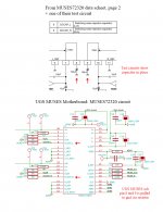
In the MUSES 72320 datasheet, pin 8 & 9, labeled DCCAP_L/DCCAP_R (Switching Noise Rejection Capacitor) has a 100uF capacitor in place in all of their test and example circuits.
Checking the UGS MUSES sch, pin 8 & 9 is pulled to gnd via 0 ohm resistor.
Why does the schematic not use a capacitor but rather a resistor ?
(see attached image)
I was inspecting the motherboard sch and found something that I can't understand. So maybe someone can jump in an explain.
In the MUSES 72320 datasheet, pin 8 & 9, labeled DCCAP_L/DCCAP_R (Switching Noise Rejection Capacitor) has a 100uF capacitor in place in all of their test and example circuits.
Checking the UGS MUSES sch, pin 8 & 9 is pulled to gnd via 0 ohm resistor.
Why does the schematic not use a capacitor but rather a resistor ?
(see attached image)
Attachments
Is the notion that the power supply is of adequate quality so that Switching Noise Rejection Capacitor is not needed at pin 8 & 9 ?
- Ceramic XR7 /Tantalum will become C0G capacitor.
- Metal Foil caps will remain.
- Thick Film Resistors 100ppm/C will become Thin Film 5-10ppm/C
- The common size will be 1206
- Through hole components will be limited to a minimum, but friendly size is kept in mind.
- Metal Foil caps will remain.
- Thick Film Resistors 100ppm/C will become Thin Film 5-10ppm/C
- The common size will be 1206
- Through hole components will be limited to a minimum, but friendly size is kept in mind.
Its settled then. The PSU's will be shielded R-Core transformers. Each chn will use 1 and the MCU and front portion will use 1, so that is 3 in total. 30VA is the smallest size which is easy to get a hold of, so 3*30VA it will be.
What really made Millennium Amplifier different was the volume attenuator wheel. It had a very lush and firm feeling. Nothing obscured the rotation and it felt like it could spin for ever, there where no mechanical input and no play - it was rock solid. I first encountered this amp back in 1999 and I still remember to this day the feeling, in other words, I got obsessed with it.
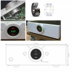
I know the important part of this project is the electronics but do you have a plan to replicate this knob design? Or something similar? What encoder will you use?
Hello and nice of you to drop in. To answer your first question: Yes that is the intention. The answer to the second question is; I am leaning towards Vishay TCUT1600x01 or use 2x Vishay TCST1103. No matter, there must be two sensors to detect direction of the rotation which is governed by which is blocked first.I know the important part of this project is the electronics but do you have a plan to replicate this knob design? Or something similar? What encoder will you use?
Regarding the bearing. I remember the salesperson mentioning that the bearing was from NASA... lol. I didn't know much about anything back then, so I took it for what it was. A "SPECIAL" bearing. In a way it is, but its not from NASA. What it is, is a double row ball bearing - TACT in their marketing material which I found a year or so back stated this themselves -, and if it is of decent quality, then you will have that lush rotation. Having some weight to the mechanism helps as well. I did consider checking if Rolls Royce maybe had such a bearing, but turns out they are using SKF in their own products so... if its good enough for them, then its good enough for me 🙂 -Anyway, the SKF variant I am looking at which you can see in the picture is closed-off, meaning self lubricated.

To anyone who have no idea or just wondering, see attached images of the unit which is the inspiration.
Attachments
Last edited:
For sure, but I think I have it figured out 😉 - It will come or be published in time, but for now, its better to have one engineer than 10 working on the same problem 🙂OK sounds interesting! Also sounds like quite some design is required for this super knob 🙂
- Home
- Source & Line
- Analog Line Level
- UGS MUSES Scion Preamplifier