Cool... Looks like we share the same fundamental idea about fully discrete and mono architecture for the PSU section. Good call. As they say: "If its worth doing, its worth doing well" 🙂
One half of "the one in the middle" is power for the MCU, the other half...…......….power for the on/off led ! LoL 🙂
ha ha ... that is one mighty LED 😉 .. On my side of things, all of the led's and UI will be controlled and fed via the MCU, so fairly straight forward.
Hi,
I have two power On/Off led's. The spoken one was for the power-supply (power-cabinet). The On/Off led for the pre. (in it's own cabinet), is driven by the MCU.
I have two power On/Off led's. The spoken one was for the power-supply (power-cabinet). The On/Off led for the pre. (in it's own cabinet), is driven by the MCU.
Last edited:
I thought about separate PSU cabinet, however, using R-core (which in itself is better shielded than a ferrite core) together with the shielding and potting should be enough, after all, the transformers will be housed inside their own compartment (Faraday cage) in the front or close to the front of the unit and should provide an equal amount of RF and EMF shielding as a separate unit. The amp side will only be exposed to DC. The incoming AC line will also be shielded from the DC side in a similar manor. That way, the whole preamp is one unit which save space.
Panasonic offers the TX2-5V relay as SMD in the form of TX2SA-5V. The main reason I am considering SMD is to bring all the components over to 1 plane and in so doing create a pure gnd plane underneath. I am just putting out the options.
If anyone has a comment on gnd planes, please use the opportunity to speak.
Oneminde
If anyone has a comment on gnd planes, please use the opportunity to speak.
Oneminde
Just remembered the voltage regulator offered through the diyaudio store... just a to have it as an option, that's all.
Super Regulator – diyAudio Store
Super Regulator – diyAudio Store
MUSES front end.
I was looking through the Stereophile review of the XP-30 and read something that puzzled me for a bit.
I was looking through the Stereophile review of the XP-30 and read something that puzzled me for a bit.
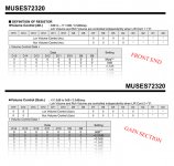
So I opened the data sheet of the MUSES and sure enough, there are two distinct functions. One is attenuation and one is gain. Meaning one can use the chip to only attenuate the volume which is at full gain when the attenuation is 0dB. The gain is (assuming) a OP-amp stage, which effectively is its own gain stage or secondary amplifier - that is a big no no since it most likely mean you have one type of gain stage up to 0dB and another gain stage from 0dB to 31.5dB. And I am sure they have sonic or musical differences.I run the NJU72320 on ±15 volts so it has a large overload margin. I really like this part as it has no op-amps in it—I only used the front, attenuation section of the chip and not the gain setting section.
Read more at Pass Laboratories XP-30 line preamplifier Page 2 | Stereophile.com
Attachments
Big News!
As of today, unless something unforeseen should happen, the UGS MUSES Scion preamplifier will diverge in a very significant way compared to its predecessors. For two generations, the 2006 UGS preamplifier and the 2015 UGS MUSES preamplifier used the special edition UGS gain stage designed by Flatlabs. It is known as UGS3a or UGS V3. This gain stage was officially approved by Nelson Pass to be used in the DIY community and so far that was the intended gain stage for the UGS MUSES Scion. I also left the door open to include the CUGS version which use paralleled BJT's, alongside the additional or secondary gain stage designed by Flatlabs in 2015 for the UGS MUSES preamplifier. Besides the MUSES volume IC and the secondary gain stage, not much had changed.
As of 2019.08.30 this will change.
Through a private email conversation with Nelson Pass, I was given the permission to move away from the unofficial UGS gain stage and towards using an official UGS gain stage. That's correct, an official Pass Labs UGS gain stage. It is not the latest generation since that would be in direct conflict with Pass Labs current product line, this one is a few generations behind but maintain the core architecture. It simply mean that we are still using Super Symmetry (SuSy) but instead of a bipolar (BJT) output gain stage, this UGS uses MOSFETs in the output, very much like Pass Labs current line up. There are other changes to this UGS gain stage that further reduces the overall noise present. This gain stage superseded the one Flatlabs based his on. Meaning we are up two levels in terms of performance. Also, the rail or supply voltage will increase, from +/-24VDC to +/-32VDC which is what PASS use on these, meaning a higher gain.
This effectively renders the CUGS paralleled version and the secondary or complimentary gain stage obsolete. As you might remember, there were talks about this secondary stage a while back and the overall consensus is that it does very little for the overall performance. I have seen measurements with and without this stage in place. Since this is the case, spending time on incorporating it makes little to no sense.
The UGS MUSES motherboard will therefore be redesigned to accept just one gain stage. This reduces the overall amount of components and should be more coherent.
All credit goes to Nelson Pass, Wayne Colburn and Pass Labs.
Hi 🙂
You are back on the right track 😉
The UGS MUSES motherboard will therefore be redesigned to accept just one gain stage. This reduces the overall amount of components and should be more coherent.
You are back on the right track 😉
So:
You are talking about UGS 6 ?
When can we expect the schematic the papa has release for use in this Preamp ?
You are talking about UGS 6 ?
When can we expect the schematic the papa has release for use in this Preamp ?
First of all, the so called UGS6 is in use by Pass Labs and I do not have access to any schematic which show this gain stage. It would also be in direct conflict to disclose such a schematic due to the reasons explained. When asking Nelson for permission to use an official UGS gain stage, that was to allow for MOSFET gain stage (output) compared to the Bipolar gain stage used in the original UGS V3 designed by Flatlabs. This was as I mentioned a special edition.So:
You are talking about UGS 6 ?
When can we expect the schematic the papa has release for use in this Preamp ?
When I talk about an official Pass Labs or Nelson Pass UGS gain stage, I am referring to an older generation. To be specific, this gain stage is the 4th iteration, aka UGS4. This version was released before 2001. Flatlabs based his UGS V3 on an even earlier version than that, to my knowledge, and changed or adjusted the output stage to use a Bipolar (BJT) output stages. The reason for this is unknown to me, so I cannot comment.
When I contacted Nelson I was very specific that my intention was to ask for permission to use and incorporate the UGS4 gain stage. No other version, be that newer or otherwise. I have no technological or financial interest in competing against Nelson Pass, Pass Labs or Wayne Colburn. And therefor never considered to ask for the UGS6, be that permission or schematic.
I am fully aware of the fact that this forum and thread is accessible to more people than are present or members. So to disclose or publish material for products currently being manufactured and sold is unwise.
When Nelson Pass publish schematics and projects, they are either standalone, (not connected to First Watt or Pass Labs) and/or modified, because anything ells would be in direct conflict with his business. First Watt is an exception to Pass Labs since some of the First Watt products is offered to the diyaudio community when the product is discontinued. If things change in terms of function and schematic is something I cannot comment on because I simply don't know.
A more direct answer to your question is that when I have incorporated the UGS4 gain stage into the project, and made sure that everything is working in union and in a coherent manor, I will start to publish material for everyone to look at, inspect and enjoy. This is however some time away since I am in the planning stages. There are several aspects of this preamplifier which is not fully realized yet, something I "stressed" about very early on - aka it is a buildlog and I am learning as a move forward. Just because the UGS MUSES which I am basing things on was finalized and released some time ago does not mean mine is ready yet - There are still many things that can and will improve. Its almost a new preamplifier from some perspectives.
So while the UGS4 was released almost 2 decades ago, was/is available through official service manual or technical documents, I will not release or publish this. Simply because unless you have a Pass Labs product, you have no need for it. I will redo the schematic because I have to so that I can design the PCB, just like I need to for the motherboard or any other circuit which will be used. I cannot or will not prevent anyone els to release the UGS4 schematic since it was/is available to the general public. That is how I stumbled upon it.... yes, stumbled upon it. So it was not handed to me nor asked of me to incorporate the UGS4, this was all my own effort and via blessings from Nelson Pass.
While this reply is directed towards CeeVee, it is also a general announcement to anyone who is reading it fairly fresh or years into the future. 🙂
Everyone has to remember that I am a n00b or "virgin" here. Everything is new to me. I have to learn about components, schematic construction, rules of PCB layout and so forth. And because Audio and Electronics is a world FULL of complex "school of thoughts", subjective and objective opinions, its one seriously messed up world to be a part of ... 😀 - So, trying to navigate through this world takes time. And I am (almost) all alone in this, this is my project and my effort and therefore it is down to me how the end results turn out. On top of that, this is not "just another project" which for many people here, it is. To me, this preamplifier must last a few decades ... yes decades. So therefore, I opt to do it as proper as possible.
So there, I cannot be any more specific on the topic of the UGS gain stage. It will come, but you have to be patient. 🙄
Oneminde
Last edited:
I knew that my announcement that the UGS MUSES Scion preamplifier will diverge by incorporating an official Pass Labs UGS gain stage would stir up things and that people would more than likely have some questions for me. That is why I am extra cautious and specific when I talk about why, how or when - for future reference, keep this in mind.
UGS4 and UGS4x
Just a casual Sunday update.
UGS4
When looking for the main components, aka the BJT and MOSFET, I noticed that the BJTs are marked as EOL or Obsolete. Meaning this specific model will become unavailable in the future. I suggest that if you don't have these already, you should consider getting a handful so that you can match them. If you don't want to perform matching, you need at least 2 of each since there are 4 BJTs in total per UGS4, which comes out to 4 pcs NPN and 4 pcs PNP in total for both channels.
On Semiconductor BCP56 - NPN
https://www.mouser.se/ProductDetail/ON-Semiconductor-Fairchild/BCP56?qs=sGAEpiMZZMshyDBzk1%2FWi8oN7VHZ91OkXtxwK98Xvvk%3D
On Semiconductor BCP53 - PNP
https://www.mouser.se/ProductDetail...=sGAEpiMZZMshyDBzk1/Wi8oN7VHZ91OkkQykb2cB6yE=
Regarding the MOSFETs, ZVN2110 (N-chn) and ZVP2110 (P-chn) from Diodes Incorporated, these are not under any threat, so no rush. But you might as well use the opportunity to secure them while you are at it with the BJTs You need the same amount as for the BJTs - 4 pcs N-chn and 4 pcs P-chn.
Diodes Incorporated ZVN2210 - N-chn.
https://www.mouser.se/ProductDetail...=/ha2pyFaduiYZ6nYRdHT6puplGPBDZ25bwt4LvUT2gs=
Diodes Incorporated ZVP2110 - P-chn.
https://www.mouser.se/ProductDetail...=sGAEpiMZZMshyDBzk1/Wi0w8OutPcgKpAGvTKETb39o=
The JFets are as per usual going to be the Linear Systems LSK170-B and LSJ74-B - Idss will be around 8mA.
UGS4x
This is a future variant which will use N-chn JFet only. One of the primary reasons to choose an N-chn JFet architecture is that P-chn JFets aren't really being produced anymore. Linear Systems is the exception. UGS4x will therefore be a bit more future friendly and one can experiment with other JFets.
Oneminde
PSU and voltage regulation.
There are two sections in this entry, one if for the PSU unit and one is for the Voltage regulation at the amplification stage.
PSU.
- Full credit her goes to Jhofland, AKSA and xkr971 for their work and time spent on developing the product. Thank you.
Smooth Like Butter (SLB): This is the SLB Class A power supply with active bridge rectifier, a CRC filter, a capacitance multiplier (CFP topology) with built in ground loop breaker NTC and star ground hub. The standard SLB provides a dual rail system that provides up to 5A (tested) with only 1mV rms ripple under a 4A load at 37v output. Use of the LT4320 active bridge and low RDSon MOSFETs as the rectifiers means that there is almost no heat generated in the rectifier (a traditional source of large amounts of heat under heavy Class A loads). The active bridge also switches at zero crossover thereby minimizing noise generated by the rectifier. A carefully engi-neered CRC filter requiring only 2 x 15,000uF bulk caps followed by a complementary feedback pair (CFP) capacitance multiplier (Cap Mx) takes the traditional 100mV rms ripple CRC PSU down to in-audible 1mV rms ripple. You will hear the blackest of blacks in your amplifier’s background now. More details of the SLB can be found on DIYA.
1. Almost no heat dissipation or loss through the rectifier.
2. Improved voltage headroom since no 0.6v drop across the silicon rectifiers
3. Smoother inherent ripple from the rectifier since switching is active and time phased to occur at zero crossing
4. More compact since fewer and smaller bulk caps are needed
5. Lower overall cost since fewer large bulk caps are used (and we all know this is one of the most expensive parts of a Class A amp aside from the case)
6. Most importantly, improved performance relative to a traditional CRC supply with lower ripple and higher current capability.
7. as icing on the cake, the SLB provides a smooth slow ramp up to prevent mains current overload and tripping fuses, plus, it eliminates turn on speaker pop.
This unit averages 1mV rms ripple under a 4A load at 37v output.

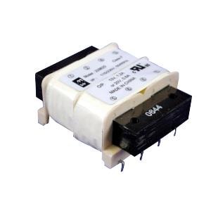
That is a superior start, and since this preamp is working in the mW range, this rectifier and ripple rejecter will not break a sweat. It will barely work at all. It will be paired with Hammond Manufacturing 229D series split core transformer. The PSU will be operated in mono configuration, each channel will use its own PSU and transformer. The MCU or controller card will only use a transformer and voltage regulator since no audio signal will pass in that unit - the AC/DC conversion for the MCU will take place in the PSU enclosure such that only DC is present in the amplification unit.
The transformers and PSU units will be placed in a separate enclosure.
Voltage Regulator.
- Full credit goes to Salas for his work and time spent on developing the product. Thank you.
Salas SSLV1.3 UltraBiB shunt regulator:
-Uses no NOS parts.
-Can do 5V to 40V output without changing a thing in its parts configuration.
-Nothing to choose and match. No tolerances in predicting its CCS limit setting.
-Has 45dB more open loop gain and many times less output impedance than 1.1
-Sounds easily better.
-Its an electrically and mechanically drop in replacement for an upgrade.
It operates in the 1-2mV range as well. The voltage regulator will be placed on the UGS motherboard instead of as a separate unit.
😀
Oneminde
There are two sections in this entry, one if for the PSU unit and one is for the Voltage regulation at the amplification stage.
PSU.
- Full credit her goes to Jhofland, AKSA and xkr971 for their work and time spent on developing the product. Thank you.
Smooth Like Butter (SLB): This is the SLB Class A power supply with active bridge rectifier, a CRC filter, a capacitance multiplier (CFP topology) with built in ground loop breaker NTC and star ground hub. The standard SLB provides a dual rail system that provides up to 5A (tested) with only 1mV rms ripple under a 4A load at 37v output. Use of the LT4320 active bridge and low RDSon MOSFETs as the rectifiers means that there is almost no heat generated in the rectifier (a traditional source of large amounts of heat under heavy Class A loads). The active bridge also switches at zero crossover thereby minimizing noise generated by the rectifier. A carefully engi-neered CRC filter requiring only 2 x 15,000uF bulk caps followed by a complementary feedback pair (CFP) capacitance multiplier (Cap Mx) takes the traditional 100mV rms ripple CRC PSU down to in-audible 1mV rms ripple. You will hear the blackest of blacks in your amplifier’s background now. More details of the SLB can be found on DIYA.
1. Almost no heat dissipation or loss through the rectifier.
2. Improved voltage headroom since no 0.6v drop across the silicon rectifiers
3. Smoother inherent ripple from the rectifier since switching is active and time phased to occur at zero crossing
4. More compact since fewer and smaller bulk caps are needed
5. Lower overall cost since fewer large bulk caps are used (and we all know this is one of the most expensive parts of a Class A amp aside from the case)
6. Most importantly, improved performance relative to a traditional CRC supply with lower ripple and higher current capability.
7. as icing on the cake, the SLB provides a smooth slow ramp up to prevent mains current overload and tripping fuses, plus, it eliminates turn on speaker pop.
This unit averages 1mV rms ripple under a 4A load at 37v output.
That is a superior start, and since this preamp is working in the mW range, this rectifier and ripple rejecter will not break a sweat. It will barely work at all. It will be paired with Hammond Manufacturing 229D series split core transformer. The PSU will be operated in mono configuration, each channel will use its own PSU and transformer. The MCU or controller card will only use a transformer and voltage regulator since no audio signal will pass in that unit - the AC/DC conversion for the MCU will take place in the PSU enclosure such that only DC is present in the amplification unit.
The transformers and PSU units will be placed in a separate enclosure.
Voltage Regulator.
- Full credit goes to Salas for his work and time spent on developing the product. Thank you.
Salas SSLV1.3 UltraBiB shunt regulator:
-Uses no NOS parts.
-Can do 5V to 40V output without changing a thing in its parts configuration.
-Nothing to choose and match. No tolerances in predicting its CCS limit setting.
-Has 45dB more open loop gain and many times less output impedance than 1.1
-Sounds easily better.
-Its an electrically and mechanically drop in replacement for an upgrade.
It operates in the 1-2mV range as well. The voltage regulator will be placed on the UGS motherboard instead of as a separate unit.
😀
Oneminde
PCB rules V1.
You know who you are 🙂 - and just wana say thank you.
In order to design the PCB, we need a few rules in place. I still have some articles and guidelines to read before I am 100% confident in my tasks ahead. But I know a few things.
Sources:
https://www.edn.com/electronics-blogs/signal-integrity/4325321/Ground-fill
LearnEMC - Some of the Worst EMC Design Guidelines
PCB plane cuts for audio paths in mixed-signal device - Electrical Engineering Stack Exchange
Oneminde
You know who you are 🙂 - and just wana say thank you.
In order to design the PCB, we need a few rules in place. I still have some articles and guidelines to read before I am 100% confident in my tasks ahead. But I know a few things.
- When possible, keep the communication (signal) on 1 plane and keep the tracks short. This effectively mean 1 layer PCB and that power and gnd (ground) is also located on this side.
- Thanks to SMD, we can now mimic the simplest form of connecting components - point-to-point (PTP).
- Not using a secondary layer reduces the plane-to-plane induction and capacitance issues. (I'm sure it has a different name)
- We can now create a ground pour or ground fill which not only is the main ground, but we can run it between our signal traces so that it limit electric forces or "signal spill" from one signal trace to another (aggressor and the victim). This reduces the amount of cross talk.
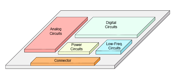
An externally hosted image should be here but it was not working when we last tested it. - The layout will also follow a fairly simple guideline in that it will be "segmented" or have regions. The power-in is the furthest away and we can even separate the different voltage lines. The MUSES chip and control circuits should be positioned closest to the output and the gain stage closest to the input - that right there are two segments... and so forth.
- And finally, we will use "star ground" so that all connections end up at this junction.
- I will also experiment with what is known as plane-cut, and this would tie into segmenting the PCB.
Sources:
https://www.edn.com/electronics-blogs/signal-integrity/4325321/Ground-fill
LearnEMC - Some of the Worst EMC Design Guidelines
PCB plane cuts for audio paths in mixed-signal device - Electrical Engineering Stack Exchange
Oneminde
- Home
- Source & Line
- Analog Line Level
- UGS MUSES Scion Preamplifier