I might end up adding a Triode stage for myself at least. I will be able to switch between the FET and Triode gain stage on the fly... No point in fighting against something a FET cannot do, replace the triode. There is a place for both FET and Triodes and having the ability to choose is the perfect solution.
UGS4 Schematic.
Its been quiet for a while, been working on a few things, including the UGS4 schematic. While I am working the UGS4 PCB, I thought i would share the schematic with you. There should be no need for any changes, but who knows 😉 - so enjoy.
Oneminde
Its been quiet for a while, been working on a few things, including the UGS4 schematic. While I am working the UGS4 PCB, I thought i would share the schematic with you. There should be no need for any changes, but who knows 😉 - so enjoy.
Oneminde
Attachments
UGS4 V1.1 has wrong pin connections - I was tired - so discard this one. I will upload the edited version tomorrow.
UGS4 V1.1b
This one uses 2x10 pin header and some of the pins are tied together. GND is present in both headers. All the nets are cleared so no errors. All values are correct. So to my knowledge, UGS V1.1b is correct. Some minor differences exist in the connection at the headers, but that should not matter for the function. Now I need to start working on the PCB, so wish me good luck 🙂
B is feedback and will be placed on the motherboard. This portion needs to be tested.
Oneminde
Attachments
Last edited:
did you try floating ground base for the Q1/Q2/Q3/Q4?This one uses 2x10 pin header and some of the pins are tied together. GND is present in both headers. All the nets are cleared so no errors. All values are correct. So to my knowledge, UGS V1.1b is correct. Some minor differences exist in the connection at the headers, but that should not matter for the function. Now I need to start working on the PCB, so wish me good luck 🙂
B is feedback and will be placed on the motherboard. This portion needs to be tested.
Oneminde
Hi. No I did not. The official UGS4 does not use floating design, so I will not use it in this reissued version either. I might explore that in another version but it will probably not be released for the official kit. Anyone is free to redesign the UGS4 as they please 🙂did you try floating ground base for the Q1/Q2/Q3/Q4?
I am also on V1.1c which is the basis for the PCB that I am currently designing. Some minor sch. changes but not much. This version including the PCB layout will be uploaded once I am done and will be open for collective remarks in terms of important flaws should there be any. It will come together with UGS4x which will be available as an option for does who are interested 😉
Oneminde
I am also on V1.1c which is the basis for the PCB that I am currently designing.
Oneminde
looking forward your new version🙂
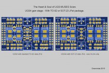
The Heart and Soul.

I started last weekend not knowing how to do proper schematics and PCB design, this was something "magical" others are able to do, but not me. But with some persistency and a pinch of determination, anything is possible. So here we are with the heart and soul of the UGS MUSES Scion preamplifier. We are now officially leaving behind the UGS used in the prior versions and entering an era of using an official PASS LABS UGS gain stage. Spite it being a few years old, it now uses MOSFETs at the output instead of BJTs. It also feature 1206 SMD resistors like I wanted.
As you can see, there are two versions of this gain stage. The normal UGS4 which use the standard TO-92 style JFets... for the hardcore Toshiba 2Sk170/2SJ74 users. For does who are a bit more adventitious there is the SOT-23 version called UGS4x which uses surface mount and N-Chn only, so no need for complimentary N- & P-Chn JFets. Designing the SOT-23 card also future-proof's the preamplifier for when the market run out of the original Toshiba JFets. I will do tests with both cards and report back.
With the gain stage designed, I can now move on to the motherboard, PSU and MCU portion of the preamplifier.
Oneminde
Attachments
Last edited:
Just found this Logic Analyzer which is hooked up to a PC - will come in handy when I debug the MCU.
Mini Saleae 16 Logic Analyzer USB
Oneminde
Mini Saleae 16 Logic Analyzer USB
Oneminde
I changed VR1/2 to multi trim pot instead of single turn. Allows for better DC offset adjustment.
I started last weekend not knowing how to do proper schematics and PCB design, this was something "magical" others are able to do, but not me. But with some persistency and a pinch of determination, anything is possible. So here we are with the heart and soul of the UGS MUSES Scion preamplifier. We are now officially leaving behind the UGS used in the prior versions and entering an era of using an official PASS LABS UGS gain stage. Spite it being a few years old, it now uses MOSFETs at the output instead of BJTs. It also feature 1206 SMD resistors like I wanted.
As you can see, there are two versions of this gain stage. The normal UGS4 which use the standard TO-92 style JFets... for the hardcore Toshiba 2Sk170/2SJ74 users. For does who are a bit more adventitious there is the SOT-23 version called UGS4x which uses surface mount and N-Chn only, so no need for complimentary N- & P-Chn JFets. Designing the SOT-23 card also future-proof's the preamplifier for when the market run out of the original Toshiba JFets. I will do tests with both cards and report back.
With the gain stage designed, I can now move on to the motherboard, PSU and MCU portion of the preamplifier.
Oneminde
waw,it is amazing,It's moving so fast.
for the VR1 and VR2,if we change to use multi turns should be better.but in my memory,this kinds of footprint only have the single turn
Best Regards
Leo
1 ). Yes, PASS use single turn only which I suspect can be a bit "rough". The new multi turn is Bourns 3296 series which has 25 turns.
2 ) If you look up On Semiconductor 2Sk3557 and look at the Id-Vdss chart and compare that to the 2SK170 and 2Sk209, you will see which one is the closest 🙂. Not only that, but the 3557 has a nominal 1dB noise figure compared to 2SK170's 0.8dB.
Also, make sure to read post 58 and 59 - I did cover some of it back then.
Oneminde
N-channel JFet's conduct in both directions - so the UGS4x only use N-chn by flipping the drain and source for one side (mirrored) 🙂GOT it,but what is replacement for the 2JS74? still have good choice for that?
Oneminde
Is there any particular reasons for not doing both channels on one card - aka just one motherboard ?
- Home
- Source & Line
- Analog Line Level
- UGS MUSES Scion Preamplifier