I totally don't have a clue of what is V6, V7 to be fully honest.
I just referred to XP-32 because the output impedance catches my interest and drove me to built this module.
In my case, I just use plain ZVN/ZVP mosfets which I paired for VGS. I also used 2sk170/2sj74.
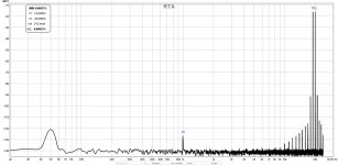
So does it sound good, to my ears definitely yes. Does it measure good, I let you judge.
Measured with RME ADI-2 PRO FS with a 10K resistive load in fully balance mode, output level is 4Vrms:

I just referred to XP-32 because the output impedance catches my interest and drove me to built this module.
In my case, I just use plain ZVN/ZVP mosfets which I paired for VGS. I also used 2sk170/2sj74.
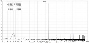
So does it sound good, to my ears definitely yes. Does it measure good, I let you judge.
Measured with RME ADI-2 PRO FS with a 10K resistive load in fully balance mode, output level is 4Vrms:

Ugs 7 will need a supply of +/- 32V.As I know in Pass XP-32 is ugs V7 with toshiba mosfets.
Ugs 7 will need a supply of +/- 32V.
like every other of his line part 🙂🤗
Not as late as some... like me.No, gionad not responding. I have done them myself and ordered yesterday.
So sad that this thread is pretty much dead. I guess I am late with my build.
Hey Pars, you are still building it and not finished yet?Not as late as some... like me.
I am still waiting for some parts, finished probably 90% but except for the PSU nothing is really complete.
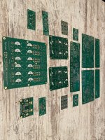
Having a bit of spare time in the last period I decided to take my chances and learn how to draw a pcb in altium. To be honest it wasn’t so difficult as I imagined initially, but when one is LAZY it finds all kind of excuses(that one being me).
Going slowly ahead I designed the pcb for the new gain stage of my preamp.
Now that I had the pcb drawn I needed to simulate the schematic to see if it works to be sure I won’t blow up something.
There was a person that encouraged me to learn ltspice and I don’t regret a sec that I followed his suggestion because the design oscillated around 1mhz and I once again want to give him a big thanks!
Seeing that soon enough I corrected the schematics and also pcbs.
All the learning process took me close to 1 month, with this I mean the time from when I placed the first component in the altium schematic and until I ordered the pcbs.
Maybe for a lot of you here this is old stuff but for me it was like discovering America 🙂
Today I received the pcbs and the next period I will try to solder them.
I have already all the parts ordered and in house.
It will be a bit difficult process because the last week the ssd on my pc died and I lost all the data so I have to go by memory, I know… bad luck but this is life.
Being lazy as I am I don’t have the will to draw everything again.
If I remember correctly for a gain of 3x(1v in/3v out) balanced I got something like 0.00008% thd, for se it was something like 0.006% this into a 10k resistive load.
can’t wait to hear it!
edit: these pcbs(left and right) are designed to be plugged in on the preamp main pcbs.
Attachments
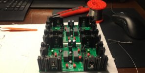
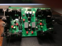
For now I finished with the soldering.
I have a few shunt regs on each pcb, the gain stage being a cascoded bba3 so even with the lost schematics it wasn’t so hard to put together.
I have a few shunt regs on each pcb, the gain stage being a cascoded bba3 so even with the lost schematics it wasn’t so hard to put together.
Attachments
Hi there , iam in a search for 2sk389bl i need 4 of them . Is any change to still have some of this??If someone need some Toshiba Fets Toshiba Dual 2SJ109BL & 2SK389BL for the UGS Preamp ge can contact me via PM. I have still enough original Toshibas.
you can buy 8 pairs of LSK170B or 2SK170BL, in Diyaudio Store
2SK389BL is pair of 2SK170BL in common case, common die
2SK389BL is pair of 2SK170BL in common case, common die
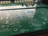
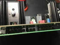
Continuing my journey with the ugs I managed to start one channel.
Using the 2.2k input filter I get 10db gain.
In the test I fed 1v and got 3v.
Unfortunately the muses chip on the second channel is dead so I can’t do any testing.
Is there someone having 2 muses chips that is willing to sell?
Using the 2.2k input filter I get 10db gain.
In the test I fed 1v and got 3v.
Unfortunately the muses chip on the second channel is dead so I can’t do any testing.
Is there someone having 2 muses chips that is willing to sell?
Attachments
If anyone could help me with those last missing parts, it would be great and highly appreciated!
1x
STMPS2151STR
SGL CHNL PWR SWTCH
1x
LM3940ISX-3.3/NOPB
1A LDO REG
2x
TPS7A3001DGNR
TI LDO Voltage Regulators
2x
F931C105KAA
16V 1uF 10% 1206 ESR Kyocera AVX Tantalum Cap
1x
STMPS2151STR
SGL CHNL PWR SWTCH
1x
LM3940ISX-3.3/NOPB
1A LDO REG
2x
TPS7A3001DGNR
TI LDO Voltage Regulators
2x
F931C105KAA
16V 1uF 10% 1206 ESR Kyocera AVX Tantalum Cap
Last edited:
Need to wait till December for this one!2x
TPS7A3001DGNR
TI LDO Voltage Regulators
It's hard time for DIY'ers nowadays...
Hi Ine, you think this is genuine? I am always very careful buying such stuff off ebay...
The LM3940ISX-3.3/NOPB I have on backorder for Nov.
The LM3940ISX-3.3/NOPB I have on backorder for Nov.
Check for MIC29310-3.3WU.
Oh, wow, its there!Check for MIC29310-3.3WU.
Any significant difference between this and the LM3940ISX-3.3/NOPB?
Will order TPS7A3001DGNR from the US seller.
Any chance for a good substitute for STMPS2151STR?
Last edited:
- Home
- Amplifiers
- Pass Labs
- UGS-muse preamp GB