The 3.3V LDO regulator is not a critical part given it is just used for the digital supply.Oh, wow, its there!
Any significant difference between this and the LM3940ISX-3.3/NOPB?
Will order TPS7A3001DGNR from the US seller.
Any chance for a good substitute for STMPS2151STR?
MIC29310-3.3WU has same package same pinnout and higher output current capability, so ....
I also found a possible substitute for the STMPS2151STR with the R5524N004A-TR-FE (in stock at Digikey but not at Mouser) .
Again, same pinnout, same package, active high enable pin same as the ST part - anyway recheck by yourself.

Hi Eric.The 3.3V LDO regulator is not a critical part given it is just used for the digital supply.
MIC29310-3.3WU has same package same pinnout and higher output current capability, so ....
I also found a possible substitute for the STMPS2151STR with the R5524N004A-TR-FE (in stock at Digikey but not at Mouser) .
Again, same pinnout, same package, active high enable pin same as the ST part - anyway recheck by yourself.
Do I need STMPS2151STR if I used dual OLED? From drawing, STMPS2151STR is applied for VFD.
Bruce Lee.
Hi Bruce Lee,Hi Eric.
Do I need STMPS2151STR if I used dual OLED? From drawing, STMPS2151STR is applied for VFD.
Bruce Lee.
You are correct, you don't need this part for a dual OLED display configuration (see note 3 in the BOM: U16 is used for VFD type display, leave unpopulated for OLED).
https://canada.newark.com/stmicroel...-1ch-500ma-sot23-5/dp/13T9570?st=stmps2151strAny chance for a good substitute for STMPS2151STR?
I got three pieces from Newark. Now, I don't need it as am going dual OLED as well (is anybody not today?) 🙂You are correct, you don't need this part for a dual OLED display configuration (see note 3 in the BOM: U16 is used for VFD type display, leave unpopulated for OLED).
Thank Eric.Hi Bruce Lee,
You are correct, you don't need this part for a dual OLED display configuration (see note 3 in the BOM: U16 is used for VFD type display, leave unpopulated for OLED).
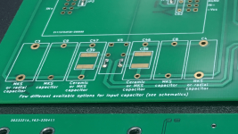
Wondering what kind of input capacitors are you guys using on the preamp boards?
Positions C3/C4, C8/C9, C38/C39, C47/C48... Thanks.
Positions C3/C4, C8/C9, C38/C39, C47/C48... Thanks.
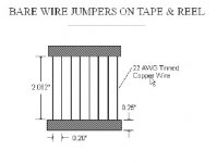
"bare wire jumpers"... ?Don’t know about others but I use this type. I think they are the best that can be used.
When I assembled my preamp pcbs I found many comments about using wire bridges in place of the input coupling caps so I followed those comments in my build. Check K5 in my attachment."bare wire jumpers"... ?
Attachments
Ok, got it.When I assembled my preamp pcbs I found many comments about using wire bridges in place of the input coupling caps so I followed those comments in my build. Check K5 in my attachment.
So you are basically not using any cap and thus bridging the relay.
I recently found some muse chips at a diyer, actually the chips found me 🙂
Yesterday I replaced both chips but the right channel the one to which I managed to blow up the muse was still not workingo I started the debugging.
First I checked that the muse got its spi signals and it did.
Then I switched the muses between them thing that confirmed that I had 2 working chips and the right preamp pcb not working.
Even if all the signals were there and the relays working I swapped the isolator and the or gate chips between them.
The problem was still there.
The muse output has always 500ohm between ground and the chip is not responsive this lead me to think that the chip is not initialized and for this I unplugged the P6 connector on the working board to see what happens. Same situation now also on the working board, the output has 500ohm between ground.
The last solution I had was to populate the ADR resistors on the right pcb as on the left one.
Doing this both pcbs work.
For the left channel I soldered r12, r14, r16 and for the right channel I soldered r11, r13, r15.
How do I need to configure correctly these resistors?
Now that I had everything working and measuring ok I pulled out from storage the dac, the amps and the speakers for the final conclusion.
Oh boy I waited a few years for this moment!
In the past I used for a few years a sony vfet front end as a line preamp which is very similar to the gain stage that I use now.
There are a few differences between one and the other main being the power supplies(which now are shunt regulators, in the past I used same ldos that we use for the muse chips voltage regulation), higher operating voltage, dc coupled.
Even if the dac puts out 4vrms which is more than enough to drive the amps, I like more the sound with the preamp connected.
Same thing I experienced also in the past with the sony fe.
I am contemplating for a long time on a blowtorch preamp but not having the original reneasas fets kept me away from the design even if it was possible to replace them with some exicon laterals.
Together with the muse chips I found also the renesas fets so now I think I will be able to build the blowtorch and compare it to the ugx.
Who knows when this will happen but for now I know for sure that I have to look for a enclosure.
ps. When I chosen the encoders I opted for the ones that ‘click’ when you rotate them. This type of encoder with dents has 32ppr only so it is able to change 16db for one complete turn.
If I want to increase or decrease the volume it takes a lot of encoder turns to get the level to where I want.
What I wanted to ask is if there is a setting somewhere that ramps up/down the volume faster when you move the encoder more than a certain number of steps in the same direction?
Lately on the forum we got a lot of designs of power followers that need a low impedance source capable to drive 20+vrms at low thd levels.
I am looking at those designs for a long time now and I always had in mind to have a preamp with those abilities.
Well seems that the ugx is able to drive a few volts in a 1k load.
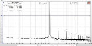
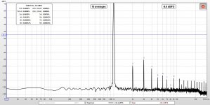
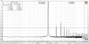
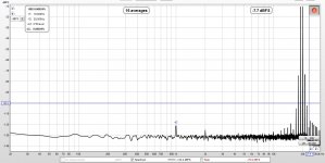
Today I did a small test.
The pre was connected to a rme dac and as loading on the output I used a 1k resistor(connected between out+ and out-) and also the focusrite adc.
I will attach some screenshots of how it went. I have the option to use switchable gain and the preamp was set for 3x and 6x.
1st attachment 2.3vin/7.5out
2nd attachment 2.3vin/14vout
3rd attachment 3.5vin/21vout
4th attachment 3.5vin/21vout
5th attachment A BIG THANKS to all specially to Papa!
I am looking at those designs for a long time now and I always had in mind to have a preamp with those abilities.
Well seems that the ugx is able to drive a few volts in a 1k load.
Today I did a small test.
The pre was connected to a rme dac and as loading on the output I used a 1k resistor(connected between out+ and out-) and also the focusrite adc.
I will attach some screenshots of how it went. I have the option to use switchable gain and the preamp was set for 3x and 6x.
1st attachment 2.3vin/7.5out
2nd attachment 2.3vin/14vout
3rd attachment 3.5vin/21vout
4th attachment 3.5vin/21vout
5th attachment A BIG THANKS to all specially to Papa!
Attachments

Got it. So you basically eliminate that additional relay in the signal path and don't use any capacitor.When I assembled my preamp pcbs I found many comments about using wire bridges in place of the input coupling caps so I followed those comments in my build. Check K5 in my attachment.
The relay can switch the capacitor off, but stays in the signal (of course) all the time... Thanks for the hint!
It mostly depends if your source exhibits dc offset. If you think you will have the possibility to encounter such situations it’s better to have those caps there because they add very low thd and will save you some trouble.
I have as a signal source only the rme dac which can be dc coupled. Also to mention that my gain module can take a dc offset of a few volts so I don’t think I need the input coupling caps.
So in the end it depends on how much you want to risk it and if it’s worth it.
Try both and see if you notice any difference and if not you can leave the caps in. My guess is you won’t notice much.
The caps itself should be defeatable via the menu (and the relay), no?It mostly depends if your source exhibits dc offset. If you think you will have the possibility to encounter such situations it’s better to have those caps there because they add very low thd and will save you some trouble.
I have as a signal source only the rme dac which can be dc coupled. Also to mention that my gain module can take a dc offset of a few volts so I don’t think I need the input coupling caps.
So in the end it depends on how much you want to risk it and if it’s worth it.
Try both and see if you notice any difference and if not you can leave the caps in. My guess is you won’t notice much.
Yes, you can choose from the menu what type of input you want to use.
If you have the time here you can find some useful info
https://www.diyaudio.com/community/...lar-caps-measured-120db-thd-140db-imd.270676/
Bypass those with 100nf wima pp and you are done.
If you have the time here you can find some useful info
https://www.diyaudio.com/community/...lar-caps-measured-120db-thd-140db-imd.270676/
Bypass those with 100nf wima pp and you are done.
- Home
- Amplifiers
- Pass Labs
- UGS-muse preamp GB