Intermodulation
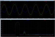
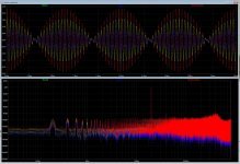
Here the preamp plays two notes of 19k and 20k. This test is really a cruel test for any amplifier and shows quite a lot.
The test is done with a bandwidth of 250kHz.
We see that the two nearest sidebands are at -80dB and we get a bar at 1kHz at -95dB.
Here the preamp plays two notes of 19k and 20k. This test is really a cruel test for any amplifier and shows quite a lot.
The test is done with a bandwidth of 250kHz.
We see that the two nearest sidebands are at -80dB and we get a bar at 1kHz at -95dB.
Attachments
Hi Johnny,
Interesting. I kind of remember, I found more or less the same results in simulation when I plotted thd vs input level. Need to redo these.
Here is some simulations plots of the module behavior in unbalanced mode (it is mine but UGS4 or UGS6 would be similar.
Interesting. I kind of remember, I found more or less the same results in simulation when I plotted thd vs input level. Need to redo these.
Here is some simulations plots of the module behavior in unbalanced mode (it is mine but UGS4 or UGS6 would be similar.
Attachments
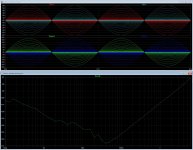
Noise.
With my "monster" power supply, there is not much noise and noise to be traced. At the same time as it plays a signal of 2V at 1kHz, the noise floor is below -130dB below 2V. This is noise free and well so it .. XP-30 has around 10dB higher noise floor.
With my "monster" power supply, there is not much noise and noise to be traced. At the same time as it plays a signal of 2V at 1kHz, the noise floor is below -130dB below 2V. This is noise free and well so it .. XP-30 has around 10dB higher noise floor.
Attachments
Noice floor
This test is not included in Stereophile's measurements of the XP30, but I included it to show how low the noise floor is also up in frequency.
And that's all the measurements I have. All measurements was done by a professional audio technician .
Conclusion.
The preamp measures very similarly to the XP-30. It has a lower noise floor, but seems to have a slightly higher distortion upwards in frequency.
Regards
Johnny
Attachments
My RME setup is unfortunately not able to measure for such low levels.
I kind of doubt, my single njfet version will be able to be as good as yours (but yours look even better than simulated one).
I kind of doubt, my single njfet version will be able to be as good as yours (but yours look even better than simulated one).
Hi Johnny,
Interesting. I kind of remember, I found more or less the same results in simulation when I plotted thd vs input level. Need to redo these.
Here is some simulations plots of the module behavior in unbalanced mode (it is mine but UGS4 or UGS6 would be similar.
Hi,
yes that looks very similar (reg.amplitude of the two phases) , when I measured mine with a SE input > Bal. out.
This was done with my chepo equipment 😱 So take these measurements with a "pinch of salt" 😉 2V, 1Khz SE in.
Phase 1: Pk-Pk : 3.48V RMS: 1.16V
Phase 2: Pk-Pk: 1.86V RMS: 620mV
My RME setup is unfortunately not able to measure for such low levels.
I kind of doubt, my single njfet version will be able to be as good as yours (but yours look even better than simulated one).
Hi,
well, all the measurments was done with top Notch expensive equipment (Rohde & Schwarz) by an Norwegian Audio engineer.
I can't for sure buy such expensive measuring equipment, but nice to have someone to do it for me 🙂
That said, he does not work for free, but it is so nice to get a pro. validation of my Diy. Worth every penny spent ! 🙂
Last edited:
Hi,
well, all the measurments was done with top Notch expensive equipment (Rohde & Schwarz) by an Norwegian Audio engineer.
I can't for sure buy such expensive measuring equipment, but nice to have someone to do it for me 🙂
That said, he does not work for free, but it is so nice to get a pro. validation of my Diy. Worth every penny spent ! 🙂
Indeed, not something I can ever compete with.🙂
I will have to stick with my modest DIY gear.
Just a last one before bed time. Here is a quick intermodulation simulation in unbalanced conditions.
Attachments
Hi,
yes that a thought. I have never measured harmonic distorsion with a Se input (with the UGS 6). Only measured with Bal. input > Bal. out.
Here is the measurement of mine (Bal.in > Bal. out with the UGS 6.
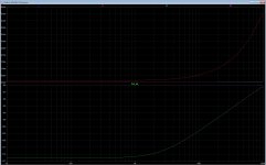
We see a small "hiccup" from my measuring instrument when it changes measuring range at 200mV. This graph is a combination of noise (N) and total harmonic distortion (THD) and tells quite a lot. Up to 2V, the noise floor (N) dominates this graph. The graph will then decrease as the signal increases. We already know that the noise floor is disappearingly low so this is more than approved. From 2V it is THD that decides and we get an increase in distortion as the signal increases. The fact that we have a minimum of around 2V fits perfectly since this is the maximum the preamp must deliver for a typical power amplifier to max out and go into cutting.
We see that it can handle "ridiculously" high 20V RMS at a distortion of only 0.02% and does not cut until around 27V rms. (38V peak !!)
Regards
Johnny
Hi Johnny,
Same overall behavior in simulation.
In my case, It starts to saturate at around 18Vpk (36V differential) but I just run it with a +/- 24V PSU.
Just a remark, the X log axis corresponds to the UGS module input signal peak amplitude (and not the output).
-- Eric
Attachments
Hi Johnny,
Same overall behavior in simulation.
In my case, It starts to saturate at around 18Vpk (36V differential) but I just run it with a +/- 24V PSU.
Just a remark, the X log axis corresponds to the UGS module input signal peak amplitude (and not the output).
-- Eric
Hi Eric06
my UGS 6 was run with the same specs. for the PSU when we did the measurements: +/- 24V
I don't remeber what the input signal peak amplitude was, when it cut at around 27V rms. (38V peak) out.
Johnny
Last edited:
Ine;6517244 [B said:Conclusion.[/B]
The preamp measures very similarly to the XP-30. It has a lower noise floor, but seems to have a slightly higher distortion upwards in frequency.
Distortion as simulated is flat until 1Khz then start to increase above.
As you can see, it is mostly H3 causing it (and unfortunately I dont have yet a solution to further reduce H3 levels at higher frequency).
This was measured in balanced mode with 10Kohms/40pf loads to GND on both OUT+ and OUT- with a 1V input amplitude (so approximately 2.8Vp/5.6V differential with my module gain setting).
Attachments
Hi Eric06
my UGS 6 was run with the same specs. for the PSU when we did the measurements: +/- 24V
I don't remeber what the input signal peak amplitude was, when it cut at around 27V rms. (38V peak) out.
Johnny
Shall it be then 38V peak to peak (13.4V RMS) ?
Hi eric06
Well, mine has the fifth harmonic as the highest is at -105dB.
Distortion as simulated is flat until 1Khz then start to increase above.
As you can see, it is mostly H3 causing it (and unfortunately I dont have yet a solution to further reduce H3 levels at higher frequency).
Well, mine has the fifth harmonic as the highest is at -105dB.
Shall it be then 38V peak to peak (13.4V RMS) ?
Hi,
sorry that is correct , 13,43 V RMS 😱
Do not put too much hype behind this module.
There is not much to be gained over an UGS3, this is just a slim incremental improvement if we put aside the main SE-BAL issue with my module.
One thing to understand is that the dc servo was just added at that time to adress tempco issue of DC offset but I had always in mind to get rid off it.
I can say, I found a solution without servo that works pretty well in simu but now I need to make another proto for verification.
I must admit, PCB artwork for this new version has been ready for sometimes but because of others activities and the SE_BAL issue, I haven't been too proactive to send it to the fab.
Bottom line, as I see it, its main advantage is that it is N-Jfet only (single pair) that works pretty well only in a BAL-BAL configuration.
I run a quick simulation with your second NTC part. No issue using it at all (nearly identical tempco results between 3500K and 3650K).
Mod Done.
i have used a B57301V2472J060 4k7 3590k NTC.
soldered "piggy back" on the res on my bib.
the test was done by modding one of the two regulators. same thermal scenario. no moving air around.
Voltages are logged.
thoose the results :

No oscillations, no strange things. the graph explains itself 🙂
thanks Eric
Mod Done.
i have used a B57301V2472J060 4k7 3590k NTC.
soldered "piggy back" on the res on my bib.
the test was done by modding one of the two regulators. same thermal scenario. no moving air around.
Voltages are logged.
thoose the results :
View attachment 920916
No oscillations, no strange things. the graph explains itself 🙂
thanks Eric
Great confirmation!
Many thanks Gionag for testing it.🙂
I will post later on today an errata to the spec with adding this ntc.
not a problem.
To be 100% correct, i have to say that i have implemented the mod on my own version of an smd ultraBib.
part's choice and components value are almost 1:1 of the one you did.
i don't expect to be too much different.
To be 100% correct, i have to say that i have implemented the mod on my own version of an smd ultraBib.
part's choice and components value are almost 1:1 of the one you did.
i don't expect to be too much different.
Well, having identify the fix though simulation, I don't expect either to see any behavioral difference between your copycat version and mine.😉
Following Gionag's validation of the tempco issue fix which appears to be effective, here is now the updated version of the shunt salas regulators board specification for the UGS muse.
For those who haven't followed, the fix just requires 2 additional thermistors and it is made to adress voltage outputs variation in temperature.😉
For those who haven't followed, the fix just requires 2 additional thermistors and it is made to adress voltage outputs variation in temperature.😉
Attachments
- Home
- Amplifiers
- Pass Labs
- UGS-muse preamp GB