With full firmware control is easily obtainable.
with what is avaiable at the moment i guess is something out of equation.
I have paused my branch of the firmware because i am trying to put the pre in its final house.
When i will go back at it is surely something worth keeping in mind to do.
thanks
with what is avaiable at the moment i guess is something out of equation.
I have paused my branch of the firmware because i am trying to put the pre in its final house.
When i will go back at it is surely something worth keeping in mind to do.
thanks
I sent the first packages today and I will send the rest next week.
The tracking numbers are available in the usual gsheet and can be used on laposte.fr
The tracking numbers are available in the usual gsheet and can be used on laposte.fr
Last edited:
hi.
will you also send the transformer and the muse chip to me?
thx
regards
slavko
edit: I already saw that you shipped the stuff... thx
will you also send the transformer and the muse chip to me?
thx
regards
slavko
edit: I already saw that you shipped the stuff... thx
Last edited:
Forgive my lazy questions, anyone utilize the triggers yet or know the following:
What contact does what on the 3.5mm socket (or plug)
Where I can find a circuit diagram for the source and amp sides of this.
What contact does what on the 3.5mm socket (or plug)
Where I can find a circuit diagram for the source and amp sides of this.
It is a bit old and kind of legacy. The UGS muse trigger was made in its initial version to be compatible with the UGS all inclusive and meant to be connected to an UP amplifier : (schematics) - The trigger receiver part is located on p4.Forgive my lazy questions, anyone utilize the triggers yet or know the following:
What contact does what on the 3.5mm socket (or plug)
Where I can find a circuit diagram for the source and amp sides of this.
How does it work?
The trigger of the UP is controlled by impulse: a pulse and I turn on, a pulse and I turn off.
This pulse should arrive on the tip end of a 3-pole jack.
The intermediate contact of the jack is a return, which lets you know whether the UP is on (5v) or off (0v).
The last contact of the jack is obviously the ground.
If I recall correctly, Alex has introduced latched outputs for the trigger in its latest firmware but I haven't really looked at it.
Last edited:
All the remaining packages will go to the postoffice today.
The gsheet has been update will the tracking numbers and also the rest to pay.
Please have a look on that, on my side I will do the refund this WE.
Alex
The gsheet has been update will the tracking numbers and also the rest to pay.
Please have a look on that, on my side I will do the refund this WE.
Alex
I’m from the first group buy and was inspired to finally finish the preamp seeing more people building the circuit. I’ve stuffed all boards and have everything working on the analog side but have hit a road block on the digital side that I need advice on.
I went to download the firmware onto the MCU but it is undetectable. I have the voltage in at 6v, voltages at regulators at 3.3v and 5v, everything as it should. I followed the procedure and placed jumper on control board, plugged in mini-USB cable then turned on power. At this point all I get from my PC is : Unknown USB Device - device detection error.
I’ve got the DFU software downloaded with the latest firmware ready to go but no DFU devices detected. I figure with the MCU unit soldered properly, all it needs is power and a clock to function?
Im assuming a dead MCU chip? I used a USB microscope to go over all the IC solders while cleaning them up, little gobs of solder liked to hide behind the legs. I did have trouble soldering the MCU in particular as I bent a couple legs while wicking and had to reposition. Don’t drag your iron across the legs while wicking!
I did purchase an extra MCU, Muse and MAX chip just in case so it’s ok if I have to replace. Just thought I’d check if maybe I missed something before I started cutting it out.
@Regland, check post#1893 or Gionag's response to it.
Either way dfuse or STM32Cubeprogrammer should work for you.
Either way dfuse or STM32Cubeprogrammer should work for you.
Last edited:
From your description, it should work. I'd take another look with your USB microscope to check all the pins. Another thing I did on mine was to ohm all adjacent pins out. And agreed on solder wick; one of mine looked a bit light on solder so I decided to try to clean it up a bit. Big mistake, with a number of bent/shorted pins, etc. Managed to fix it all and it works fine. USB microscope is a god send for these. Might have been good on the group buy to just have the pcb house pre-install these.
Hi,
Have you tried this way ?:
1) Power up
2)THEN connect the USB-cable to the computer.
I have to do it this way, to get my computer to reconice the MCU.
Johnny
Have you tried this way ?:
1) Power up
2)THEN connect the USB-cable to the computer.
I have to do it this way, to get my computer to reconice the MCU.
Johnny
Last edited:
Hello,
There is a mandatory pull down on pin PB2 (R27), without this one, DFU won't work. Just to check if you did not forget to mount it.
Ah and check if your oscillator is working, another critical point for the DFU to operate properly.
There is a mandatory pull down on pin PB2 (R27), without this one, DFU won't work. Just to check if you did not forget to mount it.
Ah and check if your oscillator is working, another critical point for the DFU to operate properly.
Thanks for the response.
Tried all of the above and still nothing. Even uninstalled dfuse and installed STM32cubeprogrammer and loaded dfu drivers. I click on the usb connect button and it gives me error:connection with device failed.
Each cap at the four corners of MCU has 3.3v so power is present. Rechecked all solders and cleaned up everything to make sure no shorts.
Don't have an oscilliscope present so can't check oscillator but can access one if necessary. Only way to check that I'm assuming? Pretty sure chip has right orientation but I wouldn't put it past me. I'm scratching my head at this point.
I'll try again tomorrow with a fresh mind.
Hi,
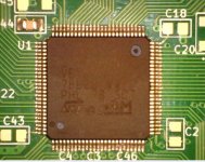
Should oriented this way:
Pretty sure chip has right orientation but I wouldn't put it past me. I'm scratching my head at this point.
Should oriented this way:
Attachments
Last edited:
What about the Reset. Did you check if it was high? If the MCU is in reset dfu won't work.
Last you can try to program with a stlink if you have access to one. Stm32 nucleo boards are really cheap and propose this feature in case you want to try.
Last you can try to program with a stlink if you have access to one. Stm32 nucleo boards are really cheap and propose this feature in case you want to try.
Replaced with new chip and still same result so must be somewhere else. I actually had right orientation phew. Thanks for confirmation Ine.
I'll try again tomorrow, thanks Alex.
I'll try again tomorrow, thanks Alex.
- Home
- Amplifiers
- Pass Labs
- UGS-muse preamp GB