CBS240 said:
.... mounting the SOT 23 parts upside down ....
.
speaking of 'upside down'
Just glue one Op-amp upside down
with pins in the air
... and so you can solder components + wires directly to pins
This works very good, if you need a circuit quick
and do not want to start messing with making boards.
( of course, do not use more heat than necessary
especially at small ICs or transistors
... not to mention LEDs ... I have melted and destroyed quite a few LEDs )
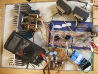
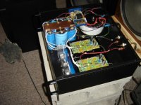
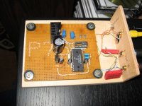
Today has been a rather boring day, so I wired up a better PS for this ugly amp, and after fiddling with the GND scheme a while the instability related to input impeadance has gone.🙂 I think GND loops are one of the most frustrating issue to deal with, and even more so on a protoboard. I thought there may be a problem with both channels input & VAS stages running from the same regulator, and there may in fact be, the next version will have seperate regulator circuits, equal mono-blocks. Anyway, the wire to one of the speakers is about 25ft 18 gauge and there is no output coil on this amp and no occilations observed😎 I will have to do the capacitor tests again to confirm. There is a 100nF cap(the little green ones at the sides) in series with a 11 Ohm resistor across the output, Av is 65 and the output clips at 16V on 4 Ohms, DMM measures DC output. Some decoupling caps beside the outputs wouldn't hurt if there was only room!
I hooked up a couple of small 'surround sound' speakers in series, reverse polarity(-+ +-) across each channel's + Vout to go with my KLH 15" 4-way's. Sound is wonderful and highs are very acurate. No PS noise or hum even with 500mV of ripple from a half wave voltage quadrupler circuit that feeds the +/-36V @ 25mA or so required for reg, input, and VAS(the little transformer on the PCB at the bottom, also producing +5V for mute control with a 7805)...I wanted to see how noisy the input voltage could be and still have good results. Now I don't want to take it apart.
 There is only a small audiable 'click' in the speakers when switching the mute on and off, no relays.
 Maybe I should build the other two channels to use the heatsink, toss it into an old flat desktop computer case and name it "The Ugly AS_ amp"
 Seriously though, if one of the solder tracks ever cracks or breaks, it could be a heck of a task to find it.🙄
I thought there may be a problem with both channels input & VAS stages running from the same regulator, and there may in fact be, the next version will have seperate regulator circuits, equal mono-blocks. Anyway, the wire to one of the speakers is about 25ft 18 gauge and there is no output coil on this amp and no occilations observed😎 I will have to do the capacitor tests again to confirm. There is a 100nF cap(the little green ones at the sides) in series with a 11 Ohm resistor across the output, Av is 65 and the output clips at 16V on 4 Ohms, DMM measures DC output. Some decoupling caps beside the outputs wouldn't hurt if there was only room!I hooked up a couple of small 'surround sound' speakers in series, reverse polarity(-+ +-) across each channel's + Vout to go with my KLH 15" 4-way's. Sound is wonderful and highs are very acurate. No PS noise or hum even with 500mV of ripple from a half wave voltage quadrupler circuit that feeds the +/-36V @ 25mA or so required for reg, input, and VAS(the little transformer on the PCB at the bottom, also producing +5V for mute control with a 7805)...I wanted to see how noisy the input voltage could be and still have good results. Now I don't want to take it apart.
There is only a small audiable 'click' in the speakers when switching the mute on and off, no relays. Maybe I should build the other two channels to use the heatsink, toss it into an old flat desktop computer case and name it "The Ugly AS_ amp" Seriously though, if one of the solder tracks ever cracks or breaks, it could be a heck of a task to find it.🙄Attachments
🙂
You have the same sort of lab experiment boards, as I have.
Plastic with holes matrix.
In this picture you can also see
a bit of my own designed Lab Supply
It is rated max 0.300A at +/-20 Volt DC unregulated.
I use it for my preamps, headphone amps and Op-Amps circuits.
Outputs:
* +/- 0-19V dual tracking symmetrical
* +8.0V
* -8.0V
* +5.00V
-------------------------------------------------
The dual tracking I can adjust:
- Coarse voltage level
- Fine voltage level adjust
- Fine tune the negative for perfect tracking positive voltage
Notice that some lab supply (LM317/LM337)
can not output lower than +/-1.25 Volt
Regards
lineup
Attachments
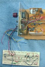
That is a handy test supply, 300mA is plenty for op-amps and headphones. Mine here is obviously temporary but serves this purpose. A bench supply is handy so you don't have to make a cheap mock up PS for each new project.🙂 My lab boards are old and well used. This kinda sucks for constructing anything complex. I just have the +/-18V output supply and the input on it. The regulators are the smallest PCB. 🙂
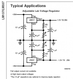
I just have the +/-18V output supply and the input on it. The regulators are the smallest PCB. 🙂you should really build yourself
a LM317/LM337 dual adjustable supply
it takes this:
1. One 2x18 0.5A, ~20 VA trafo ... they are not big
2. LM317 + LM337 in TO220 case
3. Two potentiometers
4. A few small capacitors
(LM317 / LM337 comes also in TO3 metal case, for higher powers)
There is a standard circuit for this Dual Tracking set up in the LM137 datasheet
( LM337 is an improvement of old LM137 .. like LM317 is new version of LM117 )
I guess you already knows about this. But for anybody reading this:
http://www.national.com/pf/LM/LM337.html
http://www.national.com/ds.cgi/LM/LM137.pdf
See my attachment for this simple But Very Good
dual tracking Lab supply circuit.
lineup
Attachments
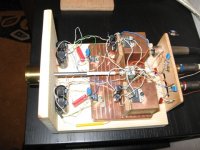
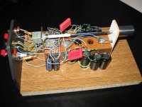
Stephen Morgan said:My GainClone. Being its mother, I think it's beautiful 😉 .
Care to guess what the base is?
😀 Hahhaha that is ugly!
Stephen Morgan said:My GainClone. Being its mother, I think it's beautiful 😉 .
Care to guess what the base is?
I think it is beautiful, too.
Have a look at those proper details!
Like: nicely twisted wires. And Wires NOT longer than necessary.
It is not that you just throw it all together.
You definitely had a plan.
And a good one!
I am sure you can figure out a nice case.
Maybe something in some beautiful wood ... 🙂
lineup
Thanks, lineup.
MJR, yes that's a clipboard. About $2 at Staples, drill out the rivets holding the clip on and you've got a fairly stable experimenting base. Just be careful with the drilling - that stuff is kinda soft.
MJR, yes that's a clipboard. About $2 at Staples, drill out the rivets holding the clip on and you've got a fairly stable experimenting base. Just be careful with the drilling - that stuff is kinda soft.
you guys obviously do not know how ugly looking amp looks like
most of those posted are quite decent
i must take picture of my Son of Zen and post it
get ready!
🙂
most of those posted are quite decent
i must take picture of my Son of Zen and post it
get ready!
🙂

adason said:you guys obviously do not know how ugly looking amp looks like
most of those posted are quite decent
i must take picture of my Son of Zen and post it
get ready!
🙂
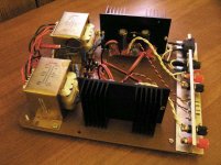
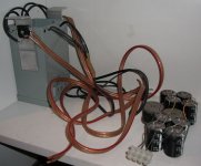
adason said:here it is, Son of Zen after years of service, /without power supply/ now retired
adason said:for completion, the power supply /withour variac, that one is in service/
adason
yes, we can say: you are right on TOPIC here!
always nice with people who understand what a thread is about 😉
I your second image, however,
that loudspeaker cable is really smelling 'Good & Adequate'
-- no problems for many Amperes to travel in that one!
lineup, regards
hehe...at least life is beautifull....because those amplifiers are really ugly
terrible...so dirty as mine ones.
regards,
Carlos
terrible...so dirty as mine ones.
regards,
Carlos
XEAGLEKEEPER said:My first DIY amp, ESP P101
Hi power version
2SK1058/2SJ162 4 pair lateral mosfet
50-0-50 800VA xformer
44,600 mfd per rail, rail voltage +/- 69.8 vdc
Igla said:My 1st regulated LM3875 GC experiment.
Ugly enough?
XEAGLEKEEPER,
if that's your first ... looking so good
I cant imagine what your other amps look like
Igla,
your amplifiers are too good looking for this thread
Maybe you should post in this thread:
'Beautiful Solid State Amps images'
instead.
But thanks - looking at nice amplifiers is always interesting.
.... so called
😀 Hard AmpCore pictures 😀
- Home
- Amplifiers
- Solid State
- UGLY Looking Amp! - but good working