Great tips Patrick. Thank you. I didn’t realize you could run the front end without the mosfets. And the taller standoffs will also give a little more space between the board and heat sink for the AlOx insulators I’m using.
"I invested in some good quality taps, used the right size drill bit for the holes, and used plenty of tapping fluid. Looking at the new holes you can’t tell them apart from the ones that came from hifi2000. 😀"
@jwjarch nice work! That is one nice looking tap holder. Do you mind sharing where you got it? I find myself doing quite a bit of drilling and tapping lately it's kinda meditative.
Jeffrey
@jwjarch nice work! That is one nice looking tap holder. Do you mind sharing where you got it? I find myself doing quite a bit of drilling and tapping lately it's kinda meditative.
Jeffrey
No problem Jeffery. Got everything on Amazon. Honestly the tap wrench could be a little better in terms of the threading that adjusts inside to hold the tap. It’s no Starret, but it was cheap and works well enough. Here are the links to everything I used for drilling and tapping the M3 holes.
uxcell Tap Wrench Handle M1-M8 Adjustable Bar Holder Straight Tapping Wrench Reamer Wrench uxcell Tap Wrench Handle M1-M8 Adjustable Bar Holder Straight Tapping Wrench Reamer Wrench - - Amazon.com
Morse Cutting Tools 38206 Metric Straight Flute Hand Tap Set, High-Speed Steel, Bright Finish, D3 Pitch Diameter Limit, 3 Flutes, M3 x 0.50 Size Morse Cutting Tools 38206 Metric Straight Flute Hand Tap Set, High-Speed Steel, Bright Finish, D3 Pitch Diameter Limit, 3 Flutes, M3 x 0.50 Size: Amazon.com: Industrial & Scientific
Mtsooning 10 Pcs 2.5mm Micro HSS Twist Drill Bit Straight Shank Electrical Drilling Tool Twist Drill Bit Set (10 pcs), Micro HSS Cobalt Drill Bit Set for Hard Metal, Stainless Steel, Cast Iron, 2.5 mm - - Amazon.com
I was asked whether the UDNeSS can be configured like a F8 :
First Watt website update
It certainly can, if that is what you wish to do.
However,
1) it does not bring about a significant performance increase; maybe half the distortion and Zout;
FIRST WATT PRODUCTS
2) it can no long take differential input, which you need if you want to have negative phase H2;
UDNeSS, or You don't need Semisouth's
3) the UDNeSS is much easier to adjust for DC offset without changing AC performance;
4) it has also been built and optimised.
So I shall leave it as an exercise if you want to simulate the single-ended version of UDNeSS as mentioned above.
Patrick
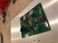
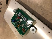
Finally finished the boards, minus the Power Mosfets - so I was trying to check the front end and make sure I have the 6mA by checking voltage across R33.
I get nothing across R33? I am testing with a small variable power supply, at +/-20Vdc with a DBT in series.
I see the +/-20Vdc at various spots across the board but could not get any voltage reading across R33, tried both boards and two different DMMs.
Neither the J113 or quad of 209s get warm to the finger, so I'm guessing they are not turning on.
I have also double checked all the parts are in the correct spots, and re-checked values with DMM. I'm fairly confident I populated the boards correctly, but a second set of eyes would be appreciated.
I did test both boards - they both perform exactly the same, nothing heats up, but also neither board has voltage across R33.
Are there other places I can take some measurements, which might help determine where my possible issue(s) are with these boards?
This is my first Class A amp, so very possible I'm not measuring accurately, or some other novice error.
Attachments


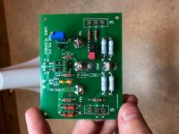
The first thing that comes to my mind is to check if you have soldered in all the necessary jumper wires? Compare it to the pics presented earlier in this thread.
Attachments
Last edited:
Your photos are too small to spot any mistakes.
But did you short +Vin and -Vin to Gnd during test ?
Patrick
But did you short +Vin and -Vin to Gnd during test ?
Patrick
Thanks guys.
I knew I missed something (easy) - totally missed that jumper thought it was for dc servo.
And I didn’t have the input shorted was just a quick test to verify it was working.
I will add jumper and give it another go with the input shorted.
I knew I missed something (easy) - totally missed that jumper thought it was for dc servo.
And I didn’t have the input shorted was just a quick test to verify it was working.
I will add jumper and give it another go with the input shorted.
It is essential to short both inputs to Gnd to make sure equal current sharing in the diff pair.
Patrick
Patrick
Thanks Patrick and Morde for the insight and assistance.
Filled the vacant jumper and tested with the inputs shorted to ground.
Works as it should - I easily set the voltage across R13 to 9.5Vdc, or ~6mA using my test power supply at +/-24Vdc.
Just waiting for the drill bits, taps and misc. things to drill and tap the holes in my heatsink (thanks jwjarch for recommendations and links). Hoping to have this sweet sounding "heater" working in a week or two.
I have been a little distracted, actually pulled my boards out this weekend and read through the thread again to recap. I do believe it is time to get my amp completed too
..dB
..dB
"I invested in some good quality taps, used the right size drill bit for the holes, and used plenty of tapping fluid. Looking at the new holes you can’t tell them apart from the ones that came from hifi2000. 😀"
@jwjarch nice work! That is one nice looking tap holder. Do you mind sharing where you got it? I find myself doing quite a bit of drilling and tapping lately it's kinda meditative.
Jeffrey
Jeffrey, I use a "2 Piece Set Ratchet Tap Wrench T-Handle Bar Type Screw Thread Tool". Got it off fleabay. Should show up on a search. I find having a ratchet allows me to keep the tap steady and plumb with the metal surface. The old school wench (for me anyway) gets too wobbly in my hand as I'm working that first quarter to half turn when you need the tap to bite into the metal.
Most fun I've had and I haven't even listened to it yet!
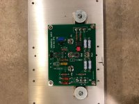
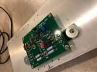
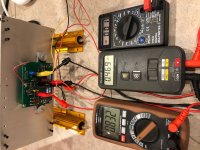
I have completed both channels of the amp, but only one channel is mounted to a heatsink (need to drill and tap the other channel). So far all my testing indicates it is working, Have run three idle tests for 15mins. (with DBT), then 30mins., then almost an hour to check for stability and temperature. Last test I dialed in the DC offset. Everything appears to be working.
I have a couple questions before I hook up speakers to it.
1) my heatsink is 10"x4-3/4"x1/4" base and 1-1/8" long fins - it gets to 55C at idle after 30-40 mins? Is this heatsink sufficient? I repurposed from a 4-channel 125w/ch Class AB Amplifier, which I thought would be plenty - however it gets HOT, and I know most would say 55C is about the limit.
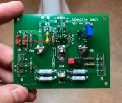
2) Bias resistors R13/R14 are slightly higher than recommended 0.56r (at 0.598) while the R11/R12 recommended 0.34r are very close at 0.3392. See pic with voltages, because even with the R13/R14 variance my calculations for the bias looks good. (0.832mV/0.5984=1.39A) and (0.469mV/0.3392=1.38A).
3) Will there be a noticeable difference connecting a single-ended RCA input, instead of an XLR, if I combine GND & -in? I don't have an XLR in my test bench, and didn't want to use an expensive Pre-Amp for the first bench test.
4) If there a "standard" O-scope test I can preform to make sure the amp is working as it should? Class AB I would run 1k & 20k at ~half wattage at 8-ohm and 4-ohm for 15-20 mins and check temperatures and for any strange sine waves
Lastly - thanks Patrick for this great amplifier - been a blast putting this together! The boards solder easily (de-solder as well), the layout makes it easy to place parts. I also learned a lot measuring and matching the parts as well as drill and tap the heatsink, first time for all of this. Let's see how I feel after I actually listen to it, I think I will have a great big dumb grin on my face - from ear to ear!
I have completed both channels of the amp, but only one channel is mounted to a heatsink (need to drill and tap the other channel). So far all my testing indicates it is working, Have run three idle tests for 15mins. (with DBT), then 30mins., then almost an hour to check for stability and temperature. Last test I dialed in the DC offset. Everything appears to be working.
I have a couple questions before I hook up speakers to it.
1) my heatsink is 10"x4-3/4"x1/4" base and 1-1/8" long fins - it gets to 55C at idle after 30-40 mins? Is this heatsink sufficient? I repurposed from a 4-channel 125w/ch Class AB Amplifier, which I thought would be plenty - however it gets HOT, and I know most would say 55C is about the limit.
2) Bias resistors R13/R14 are slightly higher than recommended 0.56r (at 0.598) while the R11/R12 recommended 0.34r are very close at 0.3392. See pic with voltages, because even with the R13/R14 variance my calculations for the bias looks good. (0.832mV/0.5984=1.39A) and (0.469mV/0.3392=1.38A).
3) Will there be a noticeable difference connecting a single-ended RCA input, instead of an XLR, if I combine GND & -in? I don't have an XLR in my test bench, and didn't want to use an expensive Pre-Amp for the first bench test.
4) If there a "standard" O-scope test I can preform to make sure the amp is working as it should? Class AB I would run 1k & 20k at ~half wattage at 8-ohm and 4-ohm for 15-20 mins and check temperatures and for any strange sine waves
Lastly - thanks Patrick for this great amplifier - been a blast putting this together! The boards solder easily (de-solder as well), the layout makes it easy to place parts. I also learned a lot measuring and matching the parts as well as drill and tap the heatsink, first time for all of this. Let's see how I feel after I actually listen to it, I think I will have a great big dumb grin on my face - from ear to ear!
Attachments
1) 55°C is OK, but you will have some additional dissipation from your rectifiers, regulators, etc.
So for long term use, I would invest in a better case. See the one I used for the J2, for example.
FirstWatt J2
2) Dissipation per FET should be around 32W max. So 1.4A means 22V rails max.
You can reduce bias by reducing R6 to say 100R, if you wish.
3) A balanced input will help to reduce noise.
It also allows you to play with the phase of second harmonics.
But you can just start with RCA first by shorting -Vin to Gnd.
4) You can use your laptop to play a 1kHz sine wave via the headphone output.
Such wav files can be downloaded online.
You can check this output signal first and adjust the volume until it is say 0.5V peak-peak.
Apply this signal to the amp, and see whether you get a 5V pk-pk output.
If yes, the amp is working.
Check it again with a dummy 8R 20W power resistor as load.
If all is fine, you may consider playing some music.
If you have expensive speakers, then I suggest adding a speaker protection circuit.
Patrick
It's playing and no issues, no turn on/off thump so far. Sounds good, I'm sure it will be better when I have both channels in a proper case and all the wiring finalized - but one speaker playing Dave Matthews Band for 15-20 mins. has a nice warm tone and I'm pretty sure I will like this amp for a while to come.
I will be ordering the 100R R6 resistors, just to bring the bias down a little lower, but will be listening to it until those come in. Hoping that will let me use these heatsinks, but we will see.
I will be ordering the 100R R6 resistors, just to bring the bias down a little lower, but will be listening to it until those come in. Hoping that will let me use these heatsinks, but we will see.
Pardon me for butting in,
Was there a previous mention that it is very desirable to use the Harris
version of the IRFP9240 or 9140? They are available at Rochester Elec.
I have actually seen some Vishay 9240's that did not have the mid band
shelving, but this was an anecdotal occurrence.

Was there a previous mention that it is very desirable to use the Harris
version of the IRFP9240 or 9140? They are available at Rochester Elec.
I have actually seen some Vishay 9240's that did not have the mid band
shelving, but this was an anecdotal occurrence.
You are always welcome, Nelson.
We did get some Harris 9240 from Rochester in a GB.
But since I wanted this project to use active devices only, we went for the Fairchild, which is a very good device.
You should give it a try, if not already.
And thanks for the info with the Vishay 9240's.
Take care in Corona time,
Patrick
We did get some Harris 9240 from Rochester in a GB.
But since I wanted this project to use active devices only, we went for the Fairchild, which is a very good device.
You should give it a try, if not already.
And thanks for the info with the Vishay 9240's.
Take care in Corona time,
Patrick
> I will be ordering the 100R R6 resistors
Order a few intermediate values, sich as 120R, 150R, 180R.
This allows you to fine adjust the bias, and match them between channels.
They don't cost anything.
Patrick
Order a few intermediate values, sich as 120R, 150R, 180R.
This allows you to fine adjust the bias, and match them between channels.
They don't cost anything.
Patrick
> I will be ordering the 100R R6 resistors
Order a few intermediate values, sich as 120R, 150R, 180R.
This allows you to fine adjust the bias, and match them between channels.
They don't cost anything.
Patrick
Great advice of course.
What approx. bias will the 100r give me?
- Home
- Amplifiers
- Solid State
- UDNeSS, or You don't need Semisouth's