so if I remove the (2) 200R SMD resistors and tack in a 500R trimmer (with center leg tied to one of the other legs) I could adjust the bias to 1.2A and test the temperatures and reduce further if needed? Then measure the resistance and replace with (2) appropriate resistors.
I cannot remember the exact version that you have now.
But assuming that you have 2x 200R in series with the LED of the optocoupler.
You can also just remove one 200R and short it.
And see what bias current you get then.
Need to adjust the trimmer at the J113 of course for DC offset.
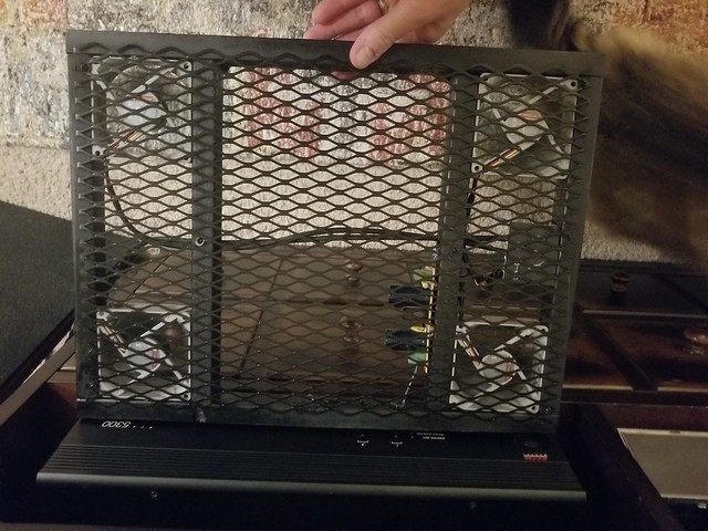
Best if you can show a photo of the bottom side of the PCB, with good resolution.
Patrick
But assuming that you have 2x 200R in series with the LED of the optocoupler.
You can also just remove one 200R and short it.
And see what bias current you get then.
Need to adjust the trimmer at the J113 of course for DC offset.
Best if you can show a photo of the bottom side of the PCB, with good resolution.
Patrick


So they are in parallel.
Together they make up 100R.
Which means you cannot just short one of them.
If you have a spare 200R, try to solder this next to the current ones.
You will then have 3x 200R in parallel, giving you 67R.
Alternatively, remote the 2x 200R and replace with a 200R trimmer set at mid-point.
Adjust bias & DC; readjust after 30 minutes; and afterwards measure the trimmer value.
Replace with fixed resistor.
Patrick
I paralleled (2) 200r and (2) 270r (only other SMDs on hand) and got 55r. This dropped the bias from 1.39 to 1.29.
Ran for 30 mins and set the DC offset. Helped the temps at 52C idle for 30 mins.
Any issue removing the R6 resistors all together and linking the pads? This should get me down to 1.2A of bias and get the temps closer to 50C (which would make me more comfortable)
Ran for 30 mins and set the DC offset. Helped the temps at 52C idle for 30 mins.
Any issue removing the R6 resistors all together and linking the pads? This should get me down to 1.2A of bias and get the temps closer to 50C (which would make me more comfortable)
You need some resistance to prevent the LED from getting accidental unlimited current.
So now you should use 2x 110R in parallel for R6.
Circuit was designed for 1.3A 24V rails.
So 1.29A is perfect.
If you need to go lower, you should really change the biasing power resistors (R11,13).
I run heatsinks at 60°C. So 55°C is no issue.
The right solution is a proper case with larger heatsinks.
Patrick
Thanks for confirming the 1.3A, I will order the proper resistors today. I will also give it a real 1-hour test tonight and see how hot the heatsinks get.
I was hoping not to disassemble my 5U case for this amp, but might be my only, or best option.
Thanks for all the help.
I was hoping not to disassemble my 5U case for this amp, but might be my only, or best option.
Thanks for all the help.
My SIT amp runs at 60degC too - been happy running daily for several months. It is well ventilated sitting on top of a rack.
You could also consider using a "babysitter" as ZenMod likes to call it - simple fan in a base to keep the airflow going.
I built this for my M2X which is in a slim chassis 3U repurposed chassis

You could also consider using a "babysitter" as ZenMod likes to call it - simple fan in a base to keep the airflow going.
I built this for my M2X which is in a slim chassis 3U repurposed chassis
I forgot to ask.
I guess you have a par of heatsinks.
Did you actually build the 2nd channel ?
And the bias are the same with 55R ?
I would listen first in stereo to determine how much I like it.
Then decide how much to invest in proper case and power supply, etc. 😉
Patrick
I guess you have a par of heatsinks.
Did you actually build the 2nd channel ?
And the bias are the same with 55R ?
I would listen first in stereo to determine how much I like it.
Then decide how much to invest in proper case and power supply, etc. 😉
Patrick
I am actually drilling and tapping the 2nd channel heatsink today.
So not sure about the bias yet, but I will certainly be matching them as close as possible.
Ordered the resistors, 4-5 different resistances, in case I need a combination to hit the 1.3A.
Listened to the one channel in the case for almost 2-hrs last night and very surprised how nice it sounds. The heatsink never got over 57C and I checked about 8 times, quickly removing the top and measuring temps. So I’m hopeful it will be fine as is.
It is fine as is, unless you have 35°C ambient in summer.
But a slow running computer fan works magic.
Just run a 12V fan with 6V.
Patrick
But a slow running computer fan works magic.
Just run a 12V fan with 6V.
Patrick
I got the 2nd channel fired up - without any issues. Bias is running high, just like the 1st channel - right at 1.41A.
I have the R6 replacement 110r resistors on order, should get both boards to ~55-ohms, which dialed the first channel to 1.3A of bias.
When this 2nd channel is up and running and have a 1-2 hour burn-in session with it, I will post a few pictures - it's going in a recycled case, with Transformer I got off the swap meet almost 6-months ago (AnTek 400VA, dual 18V secondaries) with a most likely a temporary 50V, 40,000uF PSU board.
Looking forward to seeing your build @ bullittstang. I finally have the remaining parts trickling in too - had to order the 2SK209 GR from Japan as they have been on back order for an eternity at mouser and digikey. I will match a bunch and if I have good quads, I would be more than happy to make them available to other builders, but before we go there, lets make sure I get some decent sets out of the lot I bought. I picked up the PEAK adapter too to make it more simple. Hopefully I can keep the momentum going this time 🙂 ..dB
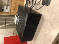
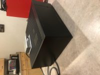
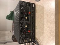
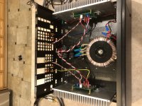
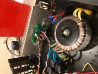
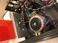
Well, here are some close to final pictures. What's in the case - 2 channels of the UDNeSS by Patrick, an AnTek 400VA 2x18V toroidal, a 50Vx40,000uF PSU (planning to upgrade) and running with RCA inputs all housed in a recycled B&K CT600.1 chassis (4U case, but heatsinks are 3U height)
I have let the amp idle for more than 2 hours with the chassis lid on - and never got over 53C (checked every 15 mins for 2 hours). I have also let it run with music at my typical listening level for over an hour 3-4 times and heat is consistent at 50-53C.
Bias is rock solid on both channels at 1.31A (ended up with 2x110r parallel for R6, or 55r to set the bias - on both channels - initially using the 2x200r for R6 they were both running high at 1.41A)
DC offset is the only odd thing - left channel starts at 0 and immediately goes to 20mV in less than 1 minute, but the right channel starts at 0 and then slowly goes to -25mV but takes ~5 mins. They both come back to 2-3mV and only fluctuate 2-3mV once warmed up (warm up takes 20-30 mins.).
Difference is the Left channel quickly comes down to 3mV, only takes 10 mins. but the right channel takes 20-30 mins to come back to ~-3mV Doesn't seem to affect anything, plays fine, no turn-on or off thump - very well behaved. Very minimal hum, which could just be the mostly temporary wiring I have in the case and not really tried any alternative grounding schemes.
Best part - it sounds so nice! As I've mentioned before, this is my first experience with a Class A amp and also my first experience with a Nelson Pass design. Very impressed and really think this amp shines with classic rock, jazz, but doesn't object to some heavy metal and Top 40 either. Wasn't sure how it was going to behave on my test speakers since they are nominally a 5-ohm load, but they have done quite well. Right now, I'm making sure I don't have any issues (DC, thermal runaway, etc.) before I hook up my higher-end DIY speakers - would hate to have an "issue" with them. Also plan to add speaker protection, but trying to figure out that, while also deciding on the PSU upgrade and do it all at the same time.
I have included some pictures - keep in mind it's 90%. Still need to figure out the additional capacitance (currently 40k uF) I have 160k uF (16-10k uF Caps) to put in the case, but I'm trying to be strategic and find the best place (and boards) to place it and the right amount (I think is 60-80k uF per channel). I am also trying to decide how to plan out the back panel, since the case is being repurposed and I think I will need to replace the back panel to use XLRs, but it sounds pretty good with RCA currently. Not sure I can stop listening long enough to completely re-work the case for XLRs - so we will see how that plays out.
Attachments


a) Many congratulations. 🙂
b) It is a reversed-polarity circuit from me based on limited information published by Nelson.
So anything not OK, you should blame me.
If it sounds good, then credit to Nelson.
c) 40mV offset is nothing for a power amp. Perfectly OK even for headphones.
d) There are many speaker protection solutions, including mine :
Simple Speaker Protection for Power Amplifier with Balanced Outputs
e) Did you try reversing both input and output ?
(+Vin to Gnd, -Vin to RCA+, Vout to Spkr-, Gnd to Spkr+)
Just follow this discussion :
UDNeSS, or You don't need Semisouth's
Patrick
Great job!
I definately recommend the balanced connection. It killed the persistent humming in my setup.
I definately recommend the balanced connection. It killed the persistent humming in my setup.
Coming back to the professionals for some insight...
Been listening to the amp for close to a week and really like the sound and starting to understand why there are so many Class A amp builders.
Thought I should try and take some measurements last night and a little confused on the results (not sure if the measurements mean everything is okay, slightly out of spec., or I have a (serious) problem):
- measured the AC across R15 with a 8V p-p output and I only get 65mV, not the documented 250mV? This was using a 1k sine wave and 8r dummy loads on both channels. Both L & R channels measured the same 65mV.
- measured peak output wattage at 8r, produced negative sine wave clipping at 11.6Vrms or 17W. If I measure up to positive sinewave clipping it measures 13.2Vrms or 21W.
- measured peak output wattage at 4r, I get 6.2Vrms or 10W at negative sine clipping, get close to 13W on positive side at clipping.
- I checked my PSU (since I only have 10kuF) and it is rock solid at +/-24.45V until hard clipping sets in and it increases to +/-24.8V. Same behaviour on both channels, I tried both channels together, then individually and has same behaviour regardless.
Thoughts (suggestions) on why AC across R15 is so much below the 250mV AC spec given?
Thoughts (suggestions) on why I am getting clipping on the negative portion of the sine wave so much earlier that the positive side?
Trying to learn as I go, so I'm willing to try most anything, including replacing parts as needed. Just not knowledgeable enough to know where to start or know what these mean to the amps performance.
> Thoughts (suggestions) on why AC across R15 is so much below the 250mV AC spec given?
AC across R15 tells you how much AC current comes from the lower FETs.
Not sure what value of R15 you are using.
The total output current would be 4V/RLoad, or 0.5A at 8R.
If the dynamic current is shared equally, then the driver FET will be providing 0.25A.
With 0.5R for R15, the dynamic voltage will be +/-125mA.
If you want to find out whether the lower FET is providing more current, you can place a 0.1R resistor between -Vs and Q4 drain.
Use the scope in AC coupled and measured the AC voltage.
You can then recalculate the dynamic current by dividing that voltage by 0.1R.
The values provided in the schematics are based on the FQA FETs used by Morde.
You can change the current ratio by changing the ratio of R11//12 and R13//14.
Best to play with it in Spice first to get an idea.
The amp is supposed to clip on the negative swing earlier than positive swing.
It is not a symmetrical amp.
But if the dynamic current is indeed largely coming from the lower FET, then it also contributes to this asymmetrical clipping.
But in normal listening, you should not be near clipping.
If you need lots of power, then this is not the right amp. 😉
P.
Last edited:
That’s a lot to take in to make an adjustment.
You don’t seem to be signaling there is an issue, so I will accept it the 0.065/0.5r=~130mA is safe and not an issue.
Very happy how the amp sounds and enjoying it. I just wanted to make sure these measurements didn’t signal a problem with my construction or lead to an imminent failure.
I have CRC PSU boards coming (China fab) and will try with double or triple the capacitance just see if there’s any audible difference.
- Home
- Amplifiers
- Solid State
- UDNeSS, or You don't need Semisouth's