This looks very interesting. Do you plan to sell the PCCBs? My apologies if this questin has already been answered. I have read the entire thread, but could have overlooked the answer to this question.
Once tested OK, we shall publish the Gerber files.
You can then use them to order your own PCB.
Lowest cost option. And no work for us.
🙂
Patrick
You can then use them to order your own PCB.
Lowest cost option. And no work for us.
🙂
Patrick
Match input pair Vgs at 3mA.
Current source requires 6~8mA.
Idss is usually ~20mA, which we shall not be using.
Hence the need to use Rdg.
To find out what value, make a small breadboard and see what resistance you need to get to 6mA.
See also :
Understanding the J113 JFET - diyAudio
Patrick
Current source requires 6~8mA.
Idss is usually ~20mA, which we shall not be using.
Hence the need to use Rdg.
To find out what value, make a small breadboard and see what resistance you need to get to 6mA.
See also :
Understanding the J113 JFET - diyAudio
Patrick
Makes perfect sense. You will have done all the hard work. Even I should be able to order the PCBs. Thanks for this project. It looks very intriguingOnce tested OK, we shall publish the Gerber files.
You can then use them to order your own PCB.
Lowest cost option. And no work for us.
🙂
Patrick
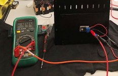
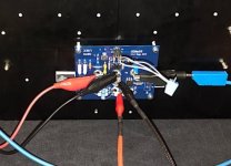
First test
First test successful.
Everything worked as intended.
🙂
Heatsink temperature 40°C after 1 hour.
DC stable to 20mV after trimming.
So servo can be optional.
Patrick
.
First test successful.
Everything worked as intended.
🙂
Heatsink temperature 40°C after 1 hour.
DC stable to 20mV after trimming.
So servo can be optional.
Patrick
.
Attachments
🙂 I forgot that your goal is a J2 mimicry.. looking forward to further development. Might need to build me a version 🙂
First test successful.
Everything worked as intended.
🙂
Heatsink temperature 40°C after 1 hour.
DC stable to 20mV after trimming.
So servo can be optional.
Patrick
.
Have you looked at the harmonic distortion spectrum already? Did you compare measured distortion spectra with the IRFs and the Semi Souths at the output?
Last edited:
Title was first test, wasn't it ?
And we are not going to compare a IRFP9240 (P-MOS) with a Semisouth (N-JFET) at the same position.
We don't know how, unless you do.
Then please kindly advise.
Patrick
And we are not going to compare a IRFP9240 (P-MOS) with a Semisouth (N-JFET) at the same position.
We don't know how, unless you do.
Then please kindly advise.
Patrick
Oups, I forgot you're using an N output. I was mainly interested in seeing measured data that support the "don't need SemiSouths" thing.
A short update.
A lot or work has been done over the weekend, without saying.
We have to make some adjustments to the circuit, as the Spice models for the MOSFETs and the JFETs do not seem accurate.
See e.g. :
JFET buffer with J113
For example, we need to adjust the R11/R13 ratio to get close to equal current sharing,
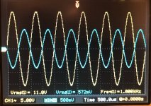
We have also measured the distortion spectrum and it is predominantly H2, with H3 20dB lower.
H4, H5 are below noise level.
But the H2 level is still a bit high for our liking, so we have a bit more fine tuning to do.
Will take a bit longer, but we are pretty sure we know how to get there.
Cheers,
Patrick
A lot or work has been done over the weekend, without saying.
We have to make some adjustments to the circuit, as the Spice models for the MOSFETs and the JFETs do not seem accurate.
See e.g. :
JFET buffer with J113
For example, we need to adjust the R11/R13 ratio to get close to equal current sharing,
We have also measured the distortion spectrum and it is predominantly H2, with H3 20dB lower.
H4, H5 are below noise level.
But the H2 level is still a bit high for our liking, so we have a bit more fine tuning to do.
Will take a bit longer, but we are pretty sure we know how to get there.
Cheers,
Patrick
- Home
- Amplifiers
- Solid State
- UDNeSS, or You don't need Semisouth's