Any new news on the amp Tekko?
I have finally built this circuit: http://i.imgur.com/8xVTPVF.png
It seems to perform really good.
this is where it gets really hard building a class D, finding fault when you don't have access to a scope.
it would be much much easier to trace the culprit if you connect it to a scope as you can't possibly check the signals just by using a multimeter.
if you have a scope check the signal output after tl071. if that's working fine check the signal output after transistor. then check the signal into the inverter. then check the signal from the inverter to the ir2110 driver. you'll pinpoint the culprit in no time.
the voltage output does swing rapidly, as it's outputting triangle and square wave.
either trace it with a scope or it's a shot in the dark. even the small paper caps close to the tl071 to generate the triangle wave have a big impact. not all type works.
by the way lower your voltage rail during troubleshooting. better still, limit the current that's going to the amp. remove any high capacity power reservoir caps and discharge any rail caps. the amp should still work with around 20-30V rail. a good working class d should only use <0.5A during operation.
limit the voltage and current and limit your risk. 80V is much too dangerous to be working with your bare hands.
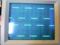
Have buy Scope and check to check IRS 4K5 , what I can see is
IR2110 Problem
HO output to Mosfet / Totem pole buffer driver, Scope show Triangle Square wave amp working,....Ho output is working
LO output from IR2110 to Mosfet / Totem pole buffer driver, Scope show nothings LO output from IR2110 is quiet ????
Is this normally ?
green Modulation LED is flashing with full power audio input, sound has very big distortion and is not loud for 80 V DC
I dont know what can do now ?
does another DIY people habe idea and solution ?
have change with another IR2110 and have chnage all ICs all the same
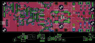
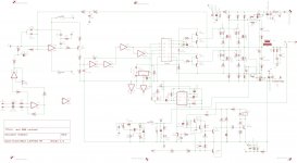
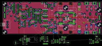
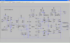
the corrected schema and the progress of manoj's double sided board aud900 😎 😎
Attachments
Last edited:
 real power extreeme power the 40kilowatts monster

no it's not normal. the LO and HO is inverted from each other. check the HIN and LIN to see the control signal being given to the IR2110. if there's no LIN signal then there's no LO signal to the mosfet.Have buy Scope and check to check IRS 4K5 , what I can see is
IR2110 Problem
HO output to Mosfet / Totem pole buffer driver, Scope show Triangle Square wave amp working,....Ho output is working
LO output from IR2110 to Mosfet / Totem pole buffer driver, Scope show nothings LO output from IR2110 is quiet ????
Is this normally ?
green Modulation LED is flashing with full power audio input, sound has very big distortion and is not loud for 80 V DC
I dont know what can do now ?
does another DIY people habe idea and solution ?
have change with another IR2110 and have chnage all ICs all the same
if there's no LIN signal but there's HIN signal then check your inverter.
nice job sir..
Sir why you use ETD 29 core??the corrected schema and the progress of manoj's double sided board aud900 😎 😎
very hard to get affordable class d core in my current location. i use e cores because i recycle them from old pc smps.
Hi,
Just out of curiosity...would like to know which is this software you are using for making schematics and boards???
Regards,
Multisim Suite 🙂
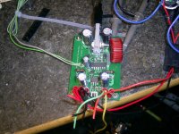
You can derive the layout quite easily from the pic of the board and from the schematic:
I also challange you to produce a layout with this exact circuit with no changes that regardless of what speaker is connected only has a barely audible hiss.
With my selection of speakers this amp can go from a barely audible hiss on some speakers to a clearly audible hiss with some crackle on other speakers, particularly on single driver fullrange speakers.
Attachments
You can derive the layout quite easily from the pic of the board and from the schematic:
I also challange you to produce a layout with this exact circuit with no changes that regardless of what speaker is connected only has a barely audible hiss.
With my selection of speakers this amp can go from a barely audible hiss on some speakers to a clearly audible hiss with some crackle on other speakers, particularly on single driver fullrange speakers.
hi tekko
what is the maximum range of applied rail to rail voltage for this amp?
With the intended mosfet (IRFB4615) max 2x60V and minimum 4 ohm load, the vreg resistors for the MAX913/TL1016 are sized accordingly.
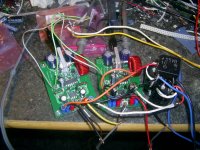
those filters helps a lot in removing EMI radiations 😀 I can see that you put them on the power lines,signal lines and output line🙂 great job!
sounds great 😀
sounds great 😀
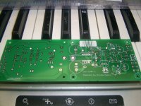
hello sir can u share ur project ...I putted together a second module:
- Home
- Amplifiers
- Class D
- UCD 25 watts to 1200 watts using 2 mosfets