Hi stewin,
for class d filter use ETD29 core with 1mm air gap( supply +75v -75v)
Regards
MANOJ
thanks manoj how many turns for 35uh ??
guyz the clear pdf artwork for the 4K5 have fun with real tested high power class d
😉😉
Attachments
An ETD29 core with a 1mm gap in the centre leg only will have an inductance factor (Al) of close to 125nH.
The equation for the total inductance (where N is the number of turns) is N^2 * Al.
So 17 turns will give you roughly 35uH.
If you are adding a 1mm gap to an ungapped core set (so the gap is in all legs), the Al will be much lower of course.
The equation for the total inductance (where N is the number of turns) is N^2 * Al.
So 17 turns will give you roughly 35uH.
If you are adding a 1mm gap to an ungapped core set (so the gap is in all legs), the Al will be much lower of course.
An ETD29 core with a 1mm gap in the centre leg only will have an inductance factor (Al) of close to 125nH.
The equation for the total inductance (where N is the number of turns) is N^2 * Al.
So 17 turns will give you roughly 35uH.
If you are adding a 1mm gap to an ungapped core set (so the gap is in all legs), the Al will be much lower of course.
thanks ouroboros
so gap in all legs it will come to how many turns to make 35uh
Last edited:
It is not a parameter that is defined in the data for the cores. This is the time to buy a low cost inductance meter perhaps?
When I get an unknown core, I wind a known number of turns on, measure the inductance and then determine Al. I then can use this value to calculate the mumber of turns needed for any required inductance on that particular core.
When I get an unknown core, I wind a known number of turns on, measure the inductance and then determine Al. I then can use this value to calculate the mumber of turns needed for any required inductance on that particular core.
An externally hosted image should be here but it was not working when we last tested it.
[/URL][/IMG]Hi stewin,
i used 40T .85mm core 1mm gap all (@70uH) fsw=250KHz cap=2.5uF/250V, cool quite
MOSFET IRFP250N with resistor 39 Ohm.
Regards
MANOJ
i used 40T .85mm core 1mm gap all (@70uH) fsw=250KHz cap=2.5uF/250V, cool quite
MOSFET IRFP250N with resistor 39 Ohm.
Regards
MANOJ
Hi stewin,thanks manoj how many turns for 35uh ??
use 28T for 35uH
regards
MANOJ
Hi stewin,
i used 40T .85mm core 1mm gap all (@70uH) fsw=250KHz cap=2.5uF/250V, cool quite
MOSFET IRFP250N with resistor 39 Ohm.
Regards
MANOJ
what voltage? and speaker impedance? did you drive hard?
thanks for reply 🙂 🙂
the component side side of pcb
thanks to ht forum
Amplificador Classe-D - Página 74
have all the fun with high power amps
" seek and you shall find "
thanks to ht forum
Amplificador Classe-D - Página 74
have all the fun with high power amps
" seek and you shall find "
Attachments
Last edited:
what voltage? and speaker impedance? did you drive hard?
Hi stewin,
Voltage +75V -75V 10A
SPK = 8Ohms 300W tested
SPK = 4Ohms 600W tested
SPK = 3x 8Ohms(Parallel) 900W tested.
Input 1.3V p-p Audio signal from mixer @ max clip level (1hr tested)
Regards
MANOJ
NANOS PCB for 3 pair
warm regards
andrew lebon
Hi andrewlebon
can I get schematic from this amp ?
have only chesthap/triell 3200 1 Ohm schematic
to add to the true spirit of diy
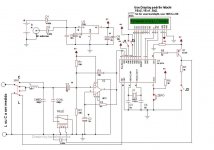
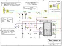
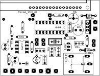
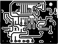
here is the inductance meter artwork, schematic and pic hex files have fun all
thanks to systemjol htforum.com

 😀😀
😀😀
here is the inductance meter artwork, schematic and pic hex files have fun all
thanks to systemjol htforum.com

 😀😀
😀😀Attachments
-
Amplificador Classe-D pg 76 lc.zip15.3 KB · Views: 819
-
 Amplificador Classe-D pg 76 jdm programmer.jpg39.4 KB · Views: 1,027
 -
 Amplificador Classe-D pg 76 lcmetertop.png11.3 KB · Views: 1,941
 -
 Amplificador Classe-D pg 76 lcmeterbot.png10.3 KB · Views: 2,222
 -
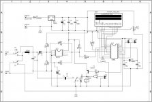 Amplificador Classe-D pg 76 lc meter esquema.jpg51.6 KB · Views: 2,283
 -
![Amplificador Classe-D pg 75 DSC_0074[1].jpg](/community/data/attachments/295/295955-74f56513095e75774f37d7cb2f0a17c6.jpg?hash=dPVlEwledX) Amplificador Classe-D pg 75 DSC_0074[1].jpg36.1 KB · Views: 2,222
Amplificador Classe-D pg 75 DSC_0074[1].jpg36.1 KB · Views: 2,222 -
![Amplificador Classe-D pg 75 DSC_0077[1].jpg](/community/data/attachments/295/295951-3dff473f7259c98953bcdc3b2b9462fb.jpg?hash=Pf9HP3JZyY) Amplificador Classe-D pg 75 DSC_0077[1].jpg33.5 KB · Views: 2,297
Amplificador Classe-D pg 75 DSC_0077[1].jpg33.5 KB · Views: 2,297
schematic of irs3000
Hi andrewlebon
can I get schematic from this amp ?
have only chesthap/triell 3200 1 Ohm schematic
Hi Nmos
greetings no schematic exists just make the pcb and put components there are different variations all work power output depends on mosfet used trying to put dc protection clipping temprature cut off on one pcb
warm regards
andrew lebon
Hi andrewlebon
can I get schematic from this amp ?
have only chesthap/triell 3200 1 Ohm schematic
Hi Nmos
greetings no schematic exists just make the pcb and put components there are different variations all work power output depends on mosfet used trying to put dc protection clipping temprature cut off on one pcb
warm regards
andrew lebon
Attachments
Andrew,Stewin, the schem the same irs900 plus 555 and lm311 OCP with 2 1oms 2w paraleled at -v rail obvius more 2 totem pole,or irs2000 plus totem schem the same tl071 4049 and ir driver for all irs models
Andrew,Stewin, the schem the same irs900 plus 555 and lm311 OCP with 2 1oms 2w paraleled at -v rail obvius more 2 totem pole,or irs2000 plus totem schem the same tl071 4049 and ir driver for all irs models
hi exflaco thanks . pls post the correct irs correct schematic with ocp protection
thanks to stewin
thanks to much
this board is so much usefull
thanks stewin
you are a good boy
to add to the true spirit of diy
here is the inductance meter artwork, schematic and pic hex files have fun all
thanks to systemjol htforum.com
😀😀
thanks to much
this board is so much usefull
thanks stewin
you are a good boy
thanks to much
this board is so much usefull
thanks stewin
you are a good boy
we thank GOD 🙂 🙂
a more clearer schematic
Attachments
Last edited:
thanks to stewin
thanks for every thinks you do for all peopel in DIY site
and thanks for clear shematic
i was buy component for this LC meter today
i will try it tomarro morning
sorry for my bad english😛we thank GOD 🙂 🙂
a more clearer schematic
thanks for every thinks you do for all peopel in DIY site
and thanks for clear shematic
i was buy component for this LC meter today
i will try it tomarro morning
- Home
- Amplifiers
- Class D
- UCD 25 watts to 1200 watts using 2 mosfets


