Heating is due to deadtime form and effective delay,i do not think the amplifier in itself has a problem.
does dead time vary with voltage ? as in the more high voltage you use the more you have to adjust dead time.? 😕 😕 and how cn one adjust ??
Thanks , you can show me that . Maybe i have some mistake 🙂
Regards
Thienchay,
Do yuo also have DIY files for the 12v bias regulator of IRS900D?...
thanks!
🙂
Yeah , i used LM317 for 1 Channel .Thienchay,
Do yuo also have DIY files for the 12v bias regulator of IRS900D?...
thanks!
🙂
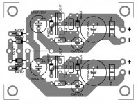
This my Layout and PDF file 🙂
Regards
Attachments
Thienchay,
Do you have the schematic? what was the appropriate values of R1 & R2?..
Andrew,
Can you post the construction details for 100uh inductor?
Thank you guys!
😉🙂
Do you have the schematic? what was the appropriate values of R1 & R2?..
Andrew,
Can you post the construction details for 100uh inductor?
Thank you guys!
😉🙂
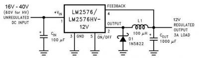
You can see all Information of LM317 in datasheet , Vout = Vref (1 + R1 / R2) + I adj R2 .Thienchay,
Do you have the schematic? what was the appropriate values of R1 & R2?..
Andrew,
Can you post the construction details for 100uh inductor?
Thank you guys!
😉🙂
You can calculate in this site : LM317 / LM338 / LM350 Voltage and Current Regulator Calculators
Thienchay,
your design gives positive 12v or 12v ref to negative supply rail.....
warm regards,,,,,
your design gives positive 12v or 12v ref to negative supply rail.....
warm regards,,,,,
Hi All
LM317 can handle only 1.5A Max. Use LM350 for 2A if you need only 1A use LM7812(700mA -- 1A Max with heat-sink) its for single IRFP250 no problem my circuit work 90V supply i use 12V regulator 7812
LM317 can handle only 1.5A Max. Use LM350 for 2A if you need only 1A use LM7812(700mA -- 1A Max with heat-sink) its for single IRFP250 no problem my circuit work 90V supply i use 12V regulator 7812
Thienchay,
your design gives positive 12v or 12v ref to negative supply rail.....
warm regards,,,,,
Hi
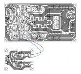
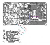
+ (12V) on Regulator Board connect to +12V on Power board
.... and - (GND) on Regulator Board connect to COM (V-) on Power Board .
GND of Regulator must be connect to V- on Power Board .
Digital deadtime no,but effective analog deadtime may vary somewhat with this schematic ,you have to measure with the scope.does dead time vary with voltage ? as in the more high voltage you use the more you have to adjust dead time.? 😕 😕 and how cn one adjust ??
But with increased voltage , switching disipasion increases also , and you should adjust deadtime at maximum used voltage for lowest THD possible and maneable disipation.
Last edited:
Hi
+ (12V) on Regulator Board connect to +12V on Power board
.... and - (GND) on Regulator Board connect to COM (V-) on Power Board .
GND of Regulator must be connect to V- on Power Board .
thanks,,,Thienchay
its negative referred....i have etch the pcb of the design which u provided...can u tell me the value of the resistor RSS and osc and also RFB....i need to know the inductance of output coil
thanks,,,Thienchay
its negative referred....i have etch the pcb of the design which u provided...can u tell me the value of the resistor RSS and osc and also RFB....i need to know the inductance of output coil
Yeah .
- RSS dependent of rail voltage you used , you can calculate it , RSS = (Volt - V(zener) / 0,01 (set 10mA passing RSS) .
+ EX : If you used +/- 75V ; RSS = (75 - 5,6) / 0,01 = 6940 , so you should used 6,8K ohm / 2W 🙂
- RFB = 100K , OSC = 1K , it set Gain .
- OCP = (V bias x R ocp / 6800 ) / R (Source MOSFET) . Set limit of output current .
+ EX : I used 12V Bias , R ocp = 220 ohm , R (Source) = 0,02 ohm ( 5 x 0,1 ohm parallel)
(12 x 220 / 6800) / 0,02 = 19,4 Ampe 🙂
Change R ocp is change limit output current .
- L output ~ 30 - 40 uH .
Last edited:
Hi Thienchay,what output mosfet can i use for +/-80V ? i was thinking at IRFB5620 (25nC gate charge) because they are class d mosfets and they are easy to drive at high speed without overheating the driver IR2110.I build a CHE900 and with IRFP4227 and 1k at oscilator i had 500Khz oscilation but the IR2110 was very hot 60-65 degrees,so i change the R OSC at 470R and got exactly 300Khz IR2110 only 40 degrees but the sound on high's was a little under the veil like something was missing.
Last edited:
ionutzxpo, is this the ROSC that you're talking about?Hi Thienchay,what output mosfet can i use for +/-80V ? i was thinking at IRFB5620 (25nC gate charge) because they are class d mosfets and they are easy to drive at high speed without overheating the driver IR2110.I build a CHE900 and with IRFP4227 and 1k at oscilator i had 500Khz oscilation but the IR2110 was very hot 60-65 degrees,so i change the R OSC at 470R and got exactly 300Khz IR2110 only 40 degrees but the sound on high's was a little under the veil like something was missing.
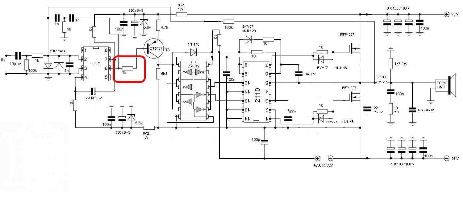
ok. thanks for the information. never knew how to change the oscillation frequency in that design before.no! its the one betwen the 1N capacitors
thanks thienchay,
will be back with the response.......could u plz tell me why dint u use totem drivers????????/
will be back with the response.......could u plz tell me why dint u use totem drivers????????/
- Home
- Amplifiers
- Class D
- UCD 25 watts to 1200 watts using 2 mosfets