che-900e is not working ir2110 ic get hot i think ic voltage com to Vdd is 5v but this schementic is give 12v
Last edited:
when using these designs....once u get succes but using same next time it causes u a failure what kind of stuff this is can anybody make it clear
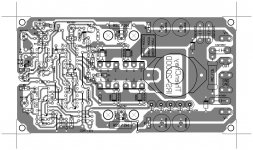
Post pcb design,all schematics on this thread work with some tweaking🙂.
Post pcb design,all schematics on this thread work with some tweaking🙂.
the irs3000d dint gave up signal out from 2n5401 and the other one just blew the **** out from IR2110....cause me to lose 5 of it in a time......the frequency was a good square wave from 2n5401 in other design...but no respose from 3000d.....inspite of the frequency on the outputs there was no response from IR.....the low output of IR gave out square wave signal but the low side was still showing something and that something was a freaking "NOTHING"
i tested these designs with +/-30volts
Attachments
Last edited:
sweet perfume you are very unlucky or maybe your ir2110 chip is bad or the aux voltage feeding the ir2110 has not reached 12vlts. happy independence day to all too.
sweet perfume you are very unlucky or maybe your ir2110 chip is bad or the aux voltage feeding the ir2110 has not reached 12vlts. happy independence day to all too.
i dint install IR2110 yet i was checking the things up that ie there everything ok...but i dont think that something ove there was ok
the irs3000d dint gave up signal out from 2n5401 and the other one just blew the **** out from IR2110....cause me to lose 5 of it in a time......the frequency was a good square wave from 2n5401 in other design...but no respose from 3000d.....inspite of the frequency on the outputs there was no response from IR.....the low output of IR gave out square wave signal but the low side was still showing something and that something was a freaking "NOTHING"
i tested these designs with +/-30volts
Traces are long,ground plane is missing,ground is not thick enough,you will have problems in high curents, but it should work ok for a few wats,if it blew form the start then you made some mistake🙁..
Last edited:
Traces are long,ground plane is missing,ground is not thick enough,you will have problems in high curents, but it should work ok for a few wats,if it blew form the start then you made some mistake🙁..
i could end up saying that i commited some mistakes but this aint the fact...i checked the design on my breadboard 100 times but there was no such mistake....the 5401 gave the clean square wave output...
"the 5401 gave the clean square wave output"
What do you mean by that? one transistor alone can not give any output..
What do you mean by that? one transistor alone can not give any output..
"the 5401 gave the clean square wave output"
What do you mean by that? one transistor alone can not give any output..
i thought u were talking about the design with TLO74....yeah u are right i dint get any output from 5401..but at which point do u think i should check out the waveforms before installing the IR2110...and can i replace cd4049 with cd4050
What amplifier are you making???..you will have NO wave forms without all the parts installed and working corectly since all the amplifiers on this thread are self oscillatting ones.
What amplifier are you making???..you will have NO wave forms without all the parts installed and working corectly since the amplifier on this thread is a self oscillatting one.
i built one of the ir2110 model but it had lot of distortion...then i got the pcb design from thienchay of irs2000d/3000d which i tried to see whether works or not...can u tell me does that work well...and what will happen if i install all the things except output fets..to see whether the IR2110 gives the high and low output correctly??????????

wire resistor
Is there any possibility that you have used wire resistor,you might have and the have inductance so use carbon ones...just a thought...
Is there any possibility that you have used wire resistor,you might have and the have inductance so use carbon ones...just a thought...
green and red led used red lights up on fault
warm regards
andrew lebon
Abeteer this pcb a mistake the 3,7v zener on lefth rail ,the catode mus be conect to gnd
abeteer sameer x1 design I think its is true
Thank you for the feedback guys 🙂
Regards!
time recent i'm so busy , so i not yet try this PCB .
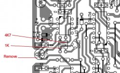
I'm temporary check , and i see R 4K7 and 1K is wrong , Detex is deceit , and i see C 100uF is not a bypass Capacitor , it connect from Ouput of TL071 to -5V6 😕 , try swap 4K7 - 1K , and remove C 100uF .
And i 'll check it soon to find a good sch and PCB , some mistake from me , sorry .
Regards .
I'm temporary check , and i see R 4K7 and 1K is wrong , Detex is deceit , and i see C 100uF is not a bypass Capacitor , it connect from Ouput of TL071 to -5V6 😕 , try swap 4K7 - 1K , and remove C 100uF .
And i 'll check it soon to find a good sch and PCB , some mistake from me , sorry .
Regards .
Attachments
- Home
- Amplifiers
- Class D
- UCD 25 watts to 1200 watts using 2 mosfets