i don't have schematic i only made the amp without it and its working great
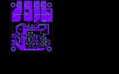
i only use detex file to make the pcb
does anyone have the correct schematic for this IRS900d?
Is this PCB correct or cointaining errors?
http://www.diyaudio.com/forums/atta...00-watts-using-2-mosfets-ab722e449ca921e4.jpg
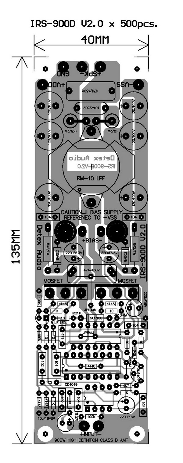
I want to use IRFP250N for this AMP as it's shown in the IRS500 layout.
I wonder if irvynejay and anyone has made this AMP help me if there is some useful points.
I want to drive the Amp with -+60 volts . should i change some parameters like RSS resistors or others?
how much should it be?
please help me by your useful tips and experiences.
with Regards.
nn20
Hi nn20
greetings just make the pcb irvynejay posted IRP 250N works on 60 volts+/-
no change of components needed
warm regards
andrew lebon
greetings just make the pcb irvynejay posted IRP 250N works on 60 volts+/-
no change of components needed
warm regards
andrew lebon
thanks to Mr lebon .and eager to read other new comments .
how much is the inductance of output inductor?
how many turns on that core( in video of irvynejay ) is needed?
i see 2 TO-220-package componnet at the bottom of PCB in that video.what are they?
how much is the inductance of output inductor?
how many turns on that core( in video of irvynejay ) is needed?
i see 2 TO-220-package componnet at the bottom of PCB in that video.what are they?
Last edited:
80uh ,irfb4227 ,gate r=10ohms
oh excuse me . I completely forget the MOSFETs which should be connected to the bottom!
80uh and 0.47uf made LPF .is it?
is it the same for IRFP250N? (amplified square waves are the same but with different domains)
Last edited:
time recent i'm so busy , so i not yet try this PCB .
I'm temporary check , and i see R 4K7 and 1K is wrong , Detex is deceit , and i see C 100uF is not a bypass Capacitor , it connect from Ouput of TL071 to -5V6 😕 , try swap 4K7 - 1K , and remove C 100uF .
And i 'll check it soon to find a good sch and PCB , some mistake from me , sorry .
Regards .
is the resistor error only prob with this pcb or something else also...and can i replace cd4049 with 4050????
the only way of knowing is for someone with better experience with class d to etch the pcb, build and test the amp.is the resistor error only prob with this pcb or something else also...and can i replace cd4049 with 4050????
the irs2000/3000d pcb didn't even come with a proper schematic so probably it would be even more helpful if someone would be good enough to trace the pcb and make a schematic out of it. that would allow people with better experience to browse and check for errors as it's quite hard to check for design error just by looking at the pcb traces.
and no you cannot replace it with cd4050 as you need an inverter.
I have made rs900. now it has a problem. one the Mosfets isn't driven and it's working by just one of these mosfets. both of them are ok. what to do?
• CD4049UB Inverting
• CD4050B Non-Inverting
then can it be used for this amp(cd4050)
irs900d
Irs900 - YouTube
plz dude post your schematics...need to know the reasons why i'm not getting the things worked up with my pcd
i had almost connected every part i guess so with irs3000d.....i would be powering it with +/-40volts.....plz give any suggestions if i would have to check out with anything serious with this pcb and schematic
is the resistor error only prob with this pcb or something else also...and can i replace cd4049 with 4050????
No , CD4050 is Non-inverting , CD4049 is Inverting Buffer .
is there any substitute for cd4049 as i dont have it at my place...any perfect one with same pin out plz help me out...i need to test the design today itself...No , CD4050 is Non-inverting , CD4049 is Inverting Buffer .
plz dude post your schematics...need to know the reasons why i'm not getting the things worked up with my pcd
i already posted i don't have schematic,, that's the only file i have i made the amp with out schematic
- Home
- Amplifiers
- Class D
- UCD 25 watts to 1200 watts using 2 mosfets