Hi luka,
look at post #95 to #105..
and I have gone through a couple of your threads, Luka.. you are very good in this subject 🙂 so please share what you have with this 🙂
regards,
Lycanlk
what? last guy said it doesn't. Do you really want to find that for yourself too?
look at post #95 to #105..
and I have gone through a couple of your threads, Luka.. you are very good in this subject 🙂 so please share what you have with this 🙂
regards,
Lycanlk
its not the schematic that is the problem(probably), its the board, you can make Damp to work just with any kind of build and it will work at low powers... but at high is where you can have problems...
Mine work ok, for low volumes, up to say 100w... but board was just too bad for any higher power, and it didn't matter if I had 2R to 8R loads, or +/-30 to 60v for supply... I think this is the same there
If not prove it and help andrewlebon
Mine work ok, for low volumes, up to say 100w... but board was just too bad for any higher power, and it didn't matter if I had 2R to 8R loads, or +/-30 to 60v for supply... I think this is the same there
If not prove it and help andrewlebon
hi savu
greetings want to ask you if the schematic really works if the circuit is ok please tell me as i am attempting d class for first time not very sure why no
output
1 voltage plus70 0 70 negative used series bulb
2 modified it like opor said changed ir 2110 4 times no one seems to have tested it at full voltage even read all pages at foros de electronica
3 any voltage readings of your amp
can you help me
thanking you
andrew lebon
hi luka
greetings have you made this amp if so what voltage did you feed it
thank you for your thought very kind of you
thanking you
andrew lebon
greetings have you made this amp if so what voltage did you feed it
thank you for your thought very kind of you
thanking you
andrew lebon
Ok i'm gonna build with my own design..
I'm not a good PCB designer.. anyway it is worth to try building this amp as it is so simple.. and thanks for the idea dear Luka.. if the schematic is fine then I can check out with different layouts..
I'll keep the space for any pro designers to make it while i'm trying my own..
regards,
Lycanlk
I'm not a good PCB designer.. anyway it is worth to try building this amp as it is so simple.. and thanks for the idea dear Luka.. if the schematic is fine then I can check out with different layouts..
I'll keep the space for any pro designers to make it while i'm trying my own..
regards,
Lycanlk
Hello all,
A friend of mine built this amp:
first try was "up in smoke"
he redesigned the PCB and built it again.
it works but it has some distortion problems when connected to anything else but a portable MP3 player.
the voltage is only +/- 28Vdc because i have to build him a smps and i haven't kept my part of the deal because of lack of time.
Now i have the time to make the smps and i also intend to make this with smd components and smd switching fets. the link below is my thread using rasmir's schematic.
http://www.diyaudio.com/forums/class-d/167147-pqfn-5x6mm-packaged-n-channel-power-mosfet-classd.html
Here are some technical data given by the author on the design of the amplifier UCD.
Distortion 0.01% to 50% power (for a 600W amplifier, a maximum of 1200W).
Low distortion even if it uses less power. And the measurement of distortion that I give is for any frequency in the audio band, from 20Hz to 20kHz! (Cleared, because many distortion amplifiers are only 1kHz, 10kHz but is much larger. It is not the case with this amp)
Output Noise: 30uV approx.
Output impedance: Of the order of 20 milliohms, or better (depending on the mosfets used)
Power Bandwidth: 0 to 23kHz (-3db) (that is to get maximum power, but the amplifier reaches much higher frequencies, just not at full power)
Voltage gain: Simply, reaches maximum power 2Vpp input signal.
Supply ripple rejection: Better than 65dB (again, depends on the components, assembly, etc)
Efficiency: Close to 92% or even less (although, again dependent on the mosfets. Probably better than the 92% for smaller powers to 1000W)
The IMD (intermodulation product is also low, with 2 modulating 19kHz and 20kHz tones, intermodulation spurious signals are smaller 80db ...
Greetings!
If it is, it have nothing what so ever to do with this design depicted in this thread, which aint a ucd what so ever. Its just another class d design by a diyer on a forum.
hi luisgrillo
greetings can you post some pictures of your pcb with components would be very helpful can i ask you something privately nothing about the amp if so please gime e mail address
thanking you
andrew lebon
greetings can you post some pictures of your pcb with components would be very helpful can i ask you something privately nothing about the amp if so please gime e mail address
thanking you
andrew lebon
Thanks everybody at least for trying..
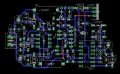
I'm still designing my own pcb.. more to think at the output stage.. (just ignore the component values there.. i need to rename them in the end)
regards.
I'm still designing my own pcb.. more to think at the output stage.. (just ignore the component values there.. i need to rename them in the end)
regards.
Attachments
Last edited:
Hi,
if I can give you a little advice.
shifts up the two mosfet and moves the pair of capacitors to below so that they can be welded directly to drain / source of the MOSFET (to VCC).
Then, the track com driver is too long and thin (this is a high inductance) Vs. source of mosfet
or shorten the approaching driver, or do the greatest thickness.
for receive "Radio Vaticano" it is good (sorry, joke)
Last edited:
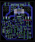
You have a big distance from IR2110 to the mosfet gates.
the ideea is to keep signal tracks and power tracks as short as possible. try to move IR2110 in front of the mosfets.
These links might help:
http://www.irf.com/technical-info/appnotes/an-1135.pdf
http://www.irf.com/technical-info/appnotes/an-978.pdf
regards,
savu silviu
the ideea is to keep signal tracks and power tracks as short as possible. try to move IR2110 in front of the mosfets.
These links might help:
http://www.irf.com/technical-info/appnotes/an-1135.pdf
http://www.irf.com/technical-info/appnotes/an-978.pdf
regards,
savu silviu
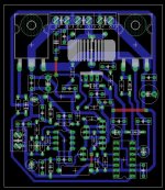
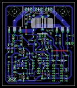
Heres my version of the board:
classdstuff :: basicclassdbrd.png picture by TheElectroNoob - Photobucket
Using regulators from the main rails, up to 35V can be used, any higher and the regulators need replacing, or removed to have an external power supply connected.
classdstuff :: basicclassdbrd.png picture by TheElectroNoob - Photobucket
Using regulators from the main rails, up to 35V can be used, any higher and the regulators need replacing, or removed to have an external power supply connected.
Last edited:
- Home
- Amplifiers
- Class D
- UCD 25 watts to 1200 watts using 2 mosfets