Hi, although i don't know the exact pricing the internal units will be a lot less than you surmised.
There are a couple of reasons for letting Stack Audio handle now. Primarily, a Group Buy takes an enormous amount of time and effort to put together. Then there is the shipping and all the follow up questions and support. Even though it was a DIY project it took virtually all of my weekends in 2020 (kept me busy during Covid at least). However, I can't sustain that level of effort any further along with my day job. 😱
Stack Audio can provide the necessary support and are geared up well to service the HiFi market. The only issue might be necessary safety approvals to sell to non EU/UK markets.
As someone who has arranged group buys in the past (and only for bulk purchase of capacitors and the like, so waaaaaay simpler than this!) I can well imagine how much time and effort this has taken up. I'm happy to hear the project will live on in a commercial environment.
Slowly stuffed the smd parts and almost ready to test the psu section.. I found a step down 230V-110V transformer I reckon I could use as an isolating trafo for the startup tests (I will then be on 230V), but.. would it be ok to test the Controller with this trafo @ final voltage/freq of 110V-50Hz?
There are a couple of reasons for letting Stack Audio handle now. Primarily, a Group Buy takes an enormous amount of time and effort to put together. Then there is the shipping and all the follow up questions and support. Even though it was a DIY project it took virtually all of my weekends in 2020 (kept me busy during Covid at least). However, I can't sustain that level of effort any further along with my day job. 😱
Have to say that I really appreciate all the effort in doing this last year, great boards and pretty much the best TT PSU fot the standard Linn/Rega Premotec motor out there. 🙂
Having said that, if Stack offer a nice anodised enclosure then I'll be jumping on that! 😀
Hi Geoturbo,
glad you are making progress. Yes its OK to use 110v to test with - so to do that install C24 (instead of the wire link) and configure the input for 110v. One you are fully tested, remove C24, install wire link and configure input for 230v. I can't remember if your kit has a three or two position input terminal block but either install the two position in the 110v & live position or solder directly. No issues if its a three way input block. If I have not given you a C24 in your kit (as you live in a 240v region), then either temporarily use one of the output capacitors or fit anything around a 22-47uf > 250v capacitor.
glad you are making progress. Yes its OK to use 110v to test with - so to do that install C24 (instead of the wire link) and configure the input for 110v. One you are fully tested, remove C24, install wire link and configure input for 230v. I can't remember if your kit has a three or two position input terminal block but either install the two position in the 110v & live position or solder directly. No issues if its a three way input block. If I have not given you a C24 in your kit (as you live in a 240v region), then either temporarily use one of the output capacitors or fit anything around a 22-47uf > 250v capacitor.
Slowly stuffed the smd parts and almost ready to test the psu section.. I found a step down 230V-110V transformer I reckon I could use as an isolating trafo for the startup tests (I will then be on 230V), but.. would it be ok to test the Controller with this trafo @ final voltage/freq of 110V-50Hz?
Thank you Steve,
currently everything psu wise seems fine, I wire-linked C24 and used 110V on 230VAC input for first startup, readings were fine so then used the trafo's 160V secondary and getting 7,99VDC at P8 and around 230VDC at TP8 so it's good to go onto next steps and reckon there should be enough Voltage I could use it like this in the next test phases for my 110V Nottingham Analogue motor
currently everything psu wise seems fine, I wire-linked C24 and used 110V on 230VAC input for first startup, readings were fine so then used the trafo's 160V secondary and getting 7,99VDC at P8 and around 230VDC at TP8 so it's good to go onto next steps and reckon there should be enough Voltage I could use it like this in the next test phases for my 110V Nottingham Analogue motor
Attachments
No connection to diode bridge.
Testing board here in US, putting 120V on the mains inputs. Only one leg of the AC gets to the diode bridge. Only the 220V connection (not now connected to AC) goes to the other AC side of the diode bridge.
I have access to v2.2b instructions but the schematic won't load on my laptop.
What is the correct DC voltage at the diode bridge output with 120VAC in?
Thanks
Pete
Hi Pete,
yes, that's correct only one leg goes to the diode bridge and the other leg to the top of C24 which forms a voltage doubler circuit. The output should be in the region of 200V - 230V. If you send me a PM with your email address I will send you another copy of the 2.2b instructions.
yes, that's correct only one leg goes to the diode bridge and the other leg to the top of C24 which forms a voltage doubler circuit. The output should be in the region of 200V - 230V. If you send me a PM with your email address I will send you another copy of the 2.2b instructions.
Testing board here in US, putting 120V on the mains inputs. Only one leg of the AC gets to the diode bridge. Only the 220V connection (not now connected to AC) goes to the other AC side of the diode bridge.
I have access to v2.2b instructions but the schematic won't load on my laptop.
What is the correct DC voltage at the diode bridge output with 120VAC in?
Thanks
Pete
Last edited:
Thank you for your response. I had zero voltage at the diode bridge DC+ out. Found a break on one leg of RT1 (now soldered). I measure 320 VDC at the bridge now.
PM sent. Thanks.
Pete
PM sent. Thanks.
Pete
Hi friends,
I have one of these PCBs, assembled by Scobham, that I won’t be using. Please PM me if you would like to buy it from me. Ships from USA.
I have one of these PCBs, assembled by Scobham, that I won’t be using. Please PM me if you would like to buy it from me. Ships from USA.
Someone will want your's. Mine is working adequately.
I don't get any rpm readouts for 33.3 or 45 but motor spins accurately.
I don't get any rpm readouts for 33.3 or 45 but motor spins accurately.
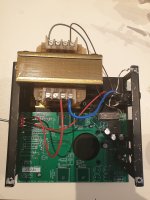
After a LOT of fannying about....I'm so slow😱...thought I'd post some pics of the controller mounted in my Heybrook TT2.
Quite pleased with myself.....for a change🙂
It looks really neat, but I'm curious about how you got the board to fit. I've got a later model TT2 with the cast sub-chassis and the 'hole' for the motor board is square and much smaller than the Zeus board.
Did you have to machine out a larger space? Because the one you've got there looks suspiciously just the right size 🙂 If so, how'd you do it...
Slowly but inesorably advancing with my build.. everything is almost built however..
When connecting Arduino to my laptop via USB, I run the PIDTuning.exe program, click on the connect button but I am not getting the serial menu out.. I tried to plug the Arduino in both of my USB ports with no luck.. suspecting I might have some driver trouble but.. is there a way to make sure for instance COMxx port is assigned to whichever USB laptop port the Arduino is connected to?
Also, in case I am able to connect it does anyone have good values of Kp Ki Kd parameters to start from? (I have a Nottingham Analogue Spacedeck standard 110V motor, thanks)
......Did you have to machine out a larger space? Because the one you've got there looks suspiciously just the right size 🙂 If so, how'd you do it...
PM'd!! 😀
No longer needed: Turntable Tachometer and motor speed controller
No longer needed: Turntable Tachometer and motor speed controller by Scobham.
I have the fully assembled board, remote IR sensor, & Oled display with button and enclosure, all assembled and supplied by Scobham.
I have used this for testing only, the controller worked perfectly, but no longer needed, I now have a different turntable.
Please PM me if you are interested in buying.
No longer available.
I have an unused fully built by Steve (Aug 2020) unit that I don't think I will be using. I would like to recover what I paid. £135 plus shipping from Perth, Australia.
Last edited:
- Home
- Group Buys
- Turntable Tachometer and motor speed controller