If the magstrip includes position data, won't you be able to calculate speed at any position?
Could very well be. I am not familiar with those.
I have seen, also here on DIYAUDIO, the hall sensor in conjunction with magnets, not with magstrip, acting as sensor for speed-measurement-and-control
Regards,
Michiel
My SW doesn't use Hilbert transforms, and methodically is different.
FWIW it was FM capture effect and lowering the 18Hz, for instance, in level and
eventually the plot "snaps" in. Not that you want to do it but one could also lower the 1KHz tone and look at the 18Hz alone. The HT is completely agnostic toward the carrier frequency and spot frequency response tracks all work fine.
The close-in noise threshold is the main difference but my tests show that a very poor SNR of the whole phono system would be necessary for there to be a real problem, in fact the out of band noise like mains hum is almost totally rejected (unless of course it is FM on the carrier).
A set of user prompts for input and basic settings is a good idea, I think any tracks that might have a problem/ambiguity could be handled.
I get plastic laser cut and engraved often enough. But I have no idea if it's precise enough to make a reference disc. Does anyone know how precise laser engravers tend to be?
Continuous wave lasers are around +/-0.002" to +/-0.004".
Then, it’s the size of the kerf which depends on the base material and it’s thickness.
Acrylic Material for Laser Cutting
POM (Polyoxymethylene) Material for Laser Cutting
Plywood Material for Laser Cutting
MDF Material for Laser Cutting
George
Correct me if I am wrong.
In LD’s software, he can see cartridge and arm behavior. It also means that you have to use a real test LP and to read it by using a real cartridge. If you use something else, what you get is the speed of platter only. There are many ways to get the platter speed. Why all the efforts?
In LD’s software, he can see cartridge and arm behavior. It also means that you have to use a real test LP and to read it by using a real cartridge. If you use something else, what you get is the speed of platter only. There are many ways to get the platter speed. Why all the efforts?
I agree....... other than for interest it seems to miss the point............Correct me if I am wrong.
In LD’s software, he can see cartridge and arm behavior. It also means that you have to use a real test LP and to read it by using a real cartridge. If you use something else, what you get is the speed of platter only. There are many ways to get the platter speed. Why all the efforts?
LD
LD, re the plots of #741, are these from my original files, or did you apply filtering on those two without (much) lo-freq content?
R.
R.
In LD’s software, he can see cartridge and arm behavior.
I think interest in separating the two is valid. The test LP method mixes all effects into one display.
I think If one replaces mat with sensor sheet one can play music record as well to get Tonearm+cartridge resonance data. Another (silly 😱) idea is to have a positive/negative postcript film of 12.5 to 13 inches with marking (I guess they can print very fine) and use it.
pardon I am little overthinking.
We can very well use cheap CD player. Put Tone Audio CD on platter. Somehow arrange CD reader (Upside down) so that it can read the test tone.
Can CD player be hacked to read data at lower speeds ? Searching the net the above idea doesn't seem that silly.sorry my mistake. a silly idea. Need to take rotational speed in to account.
Last edited:
Pardon me links are not working
Search
"scientist hack cd player transform it in to lab scanner"
"Compact Discs as Expanded Instruments: "
Search
"scientist hack cd player transform it in to lab scanner"
"Compact Discs as Expanded Instruments: "
Hi, OV - methinks you mean #641 and the posts which precede them........ but actually I didn't yet analyse or post polar plots for those files, despite being interested to do so.LD, re the plots of #741, are these from my original files, or did you apply filtering on those two without (much) lo-freq content?
R.
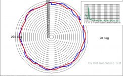
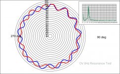
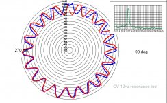
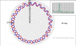
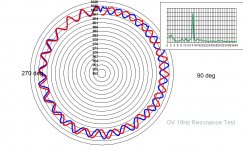
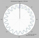
Anyways, I've found time to run them now, so here's polar plots for that series of resonance test files, which seem to be extracts from a resonance sweep, centred at 6Hz, 8Hz, 10Hz, 12Hz, 14Hz, and 16Hz. With a 1kHz carrier.
NB the scale has been changed to 0.3% per tramline, to fit in the large excursions associated with resonance.
In this case, the resonance seems to have a fairly low Q, which is a good thing IMO, and seems centred be near 10Hz.
This is always interesting IMO, because it illustrates the FM effect of cart-arm free motion, and its relatively large contribution to pitch variation in the scheme of things.
Consecutive rotations don't align in these plots, presumably because the test file stimulus is a sweep? Just by way of explanation......
Interesting ? Similar to George's test files and plots, previously posted but with lower Q.
BTW, to answer your question, no filtering is applied: the method is exceptional at rejecting out of band content.
LD
Attachments

Last edited:
How come vinyl cutting lathes achieve fantastic speed stability ?
Link : http://www.technicalaudio.com/pdf/Gordon_Clark_folder/Neumann_AM-32b_master_stereo_disk_recording_lathe_tech_notes.pdf
Also can someone explain the oil filled isolation to prevent rumble of these lathes mentioned in the link.
Thanks and regards.
Link : http://www.technicalaudio.com/pdf/Gordon_Clark_folder/Neumann_AM-32b_master_stereo_disk_recording_lathe_tech_notes.pdf
Also can someone explain the oil filled isolation to prevent rumble of these lathes mentioned in the link.
Thanks and regards.
-55 dB rumble is not so good.
unweighted, IIRC all the weighting functions reduce the low end dramatically. Thorens TD125 was -48dB unweighted for instance.
Yes, weighting drastically reduces the low end.
That sheet is from Jan 1 1959 (I remember it well). That lathe would cost about $99K in today's dollar. Not an investment made lightly. I used to run inkjet printers that cost about that much, it takes a lot of production runs to get you money back.
That sheet is from Jan 1 1959 (I remember it well). That lathe would cost about $99K in today's dollar. Not an investment made lightly. I used to run inkjet printers that cost about that much, it takes a lot of production runs to get you money back.
That lathe would cost about $99K in today's dollar. Not an investment made lightly.
Back in the 70's the folklore was that there were only one or two machinists in the country that could take on certain jobs. One was lead screws for mask steppers.
BTW, to answer your question, no filtering is applied: the method is exceptional at rejecting out of band content.
Lucky, I hope we can agree to a friendly disagreement 🙂 on the line between ignore and reject (re: filtering). The desired information is solely contained in the near sidebands of the frequency of interest all else can be either ignored or removed for the same result. I missed the type of file OV was using, ignoring extraneous information yields the same result.
Attachments
Yes, I agree the action is always near the carrier f and all that matters is that out of band content doesn't affect the outcome, be it by filtering or rejection. Good to see it work, because in practice LF content can be larger than carrier amplitude, as we've seen.The desired information is solely contained in the near sidebands of the frequency of interest all else can be either ignored or removed for the same result. I missed the type of file OV was using, ignoring extraneous information yields the same result.
LD
Thanks LD, yes, the arm-cart resonance is near 10Hz. This is no sweep, the tracks on the Test LP are dedicated tracks (1khz/16Hz, 1kHz/14Hz and so on). At 10 Hz, arm movement is massive, and somtimes the needle got catapulted out of the groove, so I'm not keen on repeating it to often...
(I fear I have to take my GT2000 on the bench, anyone happen to have a SM?)
R.
(I fear I have to take my GT2000 on the bench, anyone happen to have a SM?)
R.
That's odd, because one can see phase slip progressively around a revolution, when comparing two consecutive revs........ sure does look like a frequency sweep......... same in Scott's results too.This is no sweep, the tracks on the Test LP are dedicated tracks (1khz/16Hz, 1kHz/14Hz and so on).
Yes, looks like momentary mistracking in the raw data, once per cycle too - shows up briefly in the FM as well.At 10 Hz, arm movement is massive, and somtimes the needle got catapulted out of the groove, so I'm not keen on repeating it to often...
LD
I double checked, both by looking at phase slip between 2 successive revolutions, and by mining the FM modulating frequency at the starting segments of successive rotations: both ways it comes out as the FM modulating frequency appears to slow by ~ 0.25Hz per revolution for the 10Hz test file. Looks similar for the other test files, visually.
I think most likely the test recording was cut into segments from a longer resonance sweep track? Otherwise perhaps the TT was slowing down smoothly (??) or perhaps the headshell resonant system was beating very slowly with the resonance test............(???)
LD
I think most likely the test recording was cut into segments from a longer resonance sweep track? Otherwise perhaps the TT was slowing down smoothly (??) or perhaps the headshell resonant system was beating very slowly with the resonance test............(???)
LD
- Home
- Source & Line
- Analogue Source
- Turntable speed stabilty