Thanks for the recording, George. I have to ask - why do you record so low? You have 18-20dB headroom on that first track. Don't you want to turn it up a bit?
You are welcome Pano.
It’s not that low😀
I record 6db below the highest level of the test recording HFN S1 T9 (300Hz +18dB).
I haven’t changed settings since the beginning of the test recordings with the Stanton.
The Shure is 4dB lower than the Stanton.
🙂
George
OK, but I see it as 8dB below max for your +18dB track. That puts the other tracks very low. I know it's a 24 bit file, but I'd still record hotter.
Next post, some FFT of your new tracks
Next post, some FFT of your new tracks
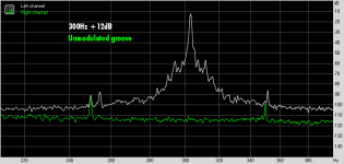
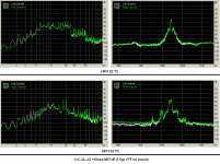
Here are some FFT plots of George's tracks from the Hi-Fi test LP.
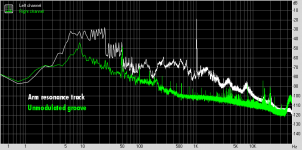
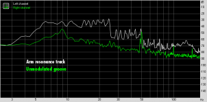
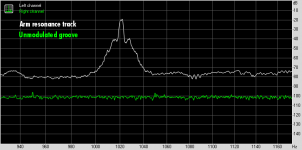
I've put the unmodulated track on the right channel, and the test signal on the left channel for comparison. The arm resonance track certainly shows disturbance.
To me it looks like the JVC was running fast, and arm resonance is around 6-7Hz. Let me know what you see. Looking forward to Lucky's polar plots of this.
Attachments


Thanks for an interesting post, Ray K - I agree, unwanted headshell motion is generally periodic, and in response to a sudden stimulus 'rings' for a time and settles. During which motion, there can be significant FM/pitch variation due to scrubbing.The only currently available test record I know that meets the criteria in option #1 is the “HiFi News & Record Review Test LP – Producer’s Cut”. Side 2, Track 2 of this disk has a resonance test that contains a fixed 1000Hz sinewave superimposed with low frequency tones swept through a range of 5Hz to 25Hz. At resonance, a spectral analysis should show the 1000Hz carrier, and 1000Hz +/- integral multiples of the mass/compliance resonance frequency.
Generally, this often shows up in polar plots, but depends on there being a suitable stimulus present. IMO the elephant in the room for stimulus is variation in stylus-groove friction, which depends on many variables such as vinyl surface, stylus profile, polish, geometric accuracy and cartridge alignment etc etc
Yes, programme material can/does, in principle, provide stimulus.
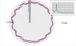
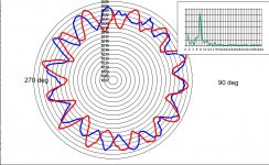
Thanks to George for providing a test recording of the HFN S2 T2 resonance sweep you mention. Attached is a polar plot of a section of George's file near 8Hz, which provides a neat continuous stimulus for headshell motion, which shows up clearly in the FM polar plot.
This shows the effect neatly, methinks.
LD
Attachments
Last edited:
Thanks Pano and Lucky.
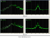
The sidebands around the 1kHz peak are quite different between S2T2 and S2T3.
George
The sidebands around the 1kHz peak are quite different between S2T2 and S2T3.
George
Here are the same tracks but through TD160 + SME3009II Impr + DL-103 (Feb 2, 2010)
1 HFN S2 T2 Cartridge-Arm Lateral resonance test (sweep).wav
https://www.dropbox.com/s/fpn3rlyo2x8p0ze/1%20HFN%20S2%20T2%20TD160.wav?dl=0
2 HFN S2 T3 Cartridge Arm Vertical resonance test (sweep).wav
https://www.dropbox.com/s/k2nxjtfsmrnps1u/2%20HFN%20S2%20T3%20TD160.wav?dl=0
3 HFN S2 T6 unmodulated groove.wav
https://www.dropbox.com/s/ptvc4ifdkm7egjd/3%20HFN%20S2%20T6%20TD160.wav?dl=0
4 HFN S1 T6 300Hz +12dB.wav
https://www.dropbox.com/s/99btew44cs090hh/4%20HFN%20S1%20T6%20TD160.wav?dl=0
George
I noticed that, too. Don't know why.The sidebands around the 1kHz peak are quite different between S2T2 and S2T3.
Thanks for the plot, Lucky. We do see the resonance in the polar.
Thanks
Thank you George for the recordings, Pano for the FFT plots, and LD for the polar plot!
Ray K
Thank you George for the recordings, Pano for the FFT plots, and LD for the polar plot!
Ray K
You're welcome, RayK - thanks for the idea of that track as stimulus !Thank you George for the recordings, Pano for the FFT plots, and LD for the polar plot!
Ray K
I realised overnight that I hadn't adjusted the polar plot radial line scale to accommodate the drop down to 1kHz. I try to keep each scale line to represent about 0.1% pitch variation - said to be about the threshold of audibility for most people.
So here's a re-plot of that polar plot of George's file JVC QL-A2 M97eX 1.5 HFN S2 T2, just the section around 8Hz.
At this (proper) scale, I think one can readily see the large significance of the cart-arm system/headshell motion to pitch stability. In this case, it even dwarfs record centring............
LD
Attachments
Take a look at the Left and Right balance with a vocal (centre channel) removal effect. I can clearly see the stereo position wobbling away from dead centre twice in a revolution, one position much stronger than the other. This means that we have stereo position modification on top of FM effectsHere is a 3150hz sample from a Phonosophie No3 turntable.
Phonosophie P3 3150Hz Tone /Phonosophie_P3_3150Hz_Tone.wav
msdin
Yes, there will be AM modulation of the R-L difference 'channel' according to the direction vector of headshell motion.Take a look at the Left and Right balance with a vocal (centre channel) removal effect. I can clearly see the stereo position wobbling away from dead centre twice in a revolution, one position much stronger than the other. This means that we have stereo position modification on top of FM effects
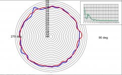
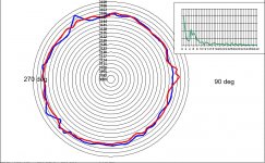
Although we discuss headshell motion as though it were vertical and lateral, in practice the system is continuous in 2D and the headshell is free to move in both lateral and vertical directions at the same time - and does so. A realistic path might be a lissajous type figure in 2D, and from moment to moment the vector might vary.
This is bad for stereo image stability, of course.
And yes, this is separate and supplementary to FM/pitch modulation, which depends simply on the relative velocity of vinyl past the stylus and is the same for both sum and difference signals, no matter what vector headshell motion has.
To show this, attached are sum (lateral) and difference (vertical) 'channel' polar plots for exactly the same section of that Phonosophie TT file - one can see they are pretty much identical, and have the same spectrum in FM. Red and Blue traces are two successive revolutions, as usual.
LD
Attachments
Might help the phantom center, tho.This is bad for stereo image stability, of course.
http://www.diyaudio.com/forums/multi-way/277519-fixing-stereo-phantom-center.html
Any chance of sharing some of this. A conversion to something more portable than VB would be worth doing?
Should be ported to Python. Then it should be possible to support the common platforms.
Do well made, rigid, tight servo controlled linear tonearms have any advantage with respect to speed stability ?
Thanks and Regards.
Thanks and Regards.
Should be ported to Python. Then it should be possible to support the common platforms.
Probably better math libs too.
I am experimenting with Octave, with fmdemod and ademodce, not exactly well documentedProbably better math libs too.
This stereo position jitter acts like dither on the comb filtering. As vocals are often mixed dead centre, LP and CD would end up sounding very differentMight help the phantom center, tho.
http://www.diyaudio.com/forums/multi-way/277519-fixing-stereo-phantom-center.html
I'm sure there's all manner of faster and more elegant implementations. But methinks you'll all find the precision low noise frequency detection algorithm is the thing of beauty here. I'd be happy to participate in an open source open licence project, if anyone is any good at arranging such things?Probably better math libs too.
I'm a spherical cow sort of dog, as everyone surely knows by now.........😉
LD
Sounds capital, Lucky! Certainly here on diyAudio there are people with these skills.
This would be a nice gift to the audio community.
This would be a nice gift to the audio community.
So here's a re-plot of that polar plot of George's file JVC QL-A2 M97eX 1.5 HFN S2 T2, just the section around 8Hz.
I like more the one you showed at post #84 😀
When time allows, can you post please the polar plot for the HFN S2 T3 as well.
Thank you again. 🙂
George
Attachments
- Home
- Source & Line
- Analogue Source
- Turntable speed stabilty