I remember there was an Elector magazine sold in the UK. It was a very good magazine.So it (simplified version) got published (Elektuur / Elektor).
Because RF design has been a hobby since ~age 12, my job at Elektuur wasn't work in the usual sense, and more so because every designer could propose a project for publication, which before realization would be discussed on aspects like performance, cost, difficulty, availability of components etc.. At a small company that meant it was never boring.
Same here, I can remember buying bits of electronics even test equipment at a very early age.
Those kinds of magazines were great for the projects and the adverts selling components etc. Elektor, Practical Wireless, Wireless World, Practical Computing etc, all great. I was interested in becoming an Amateur Radio Ham, I had short wave radios and listened to the Amateur bands. I bought all the books to do the exams but was very worried about doing the Morse code exam. Before I knew it I was in Uni studying Electronics and never got round to doing the Amateur Radio exams.
I built one of the Sinclair Micromatic radios very early on. They were advertised as the smallest radio in the world!
Last edited:
I had to read all of those magazines to keep Elektuur competitive, and the librarian even arranged subscription exchange with a Russian and an East-German magazine. But my start was with tubes, Philips A series (4V heater) like E446, E447, A415, E443H etc. With the US 75 (diode) triode I built a regenerative RX with plug in coils, adjustable in position (regeneration, antenna coupling). The headphone was loud enough for the neighbors to notice, thanks to the high solar activity.
I got a ham license in the Netherlands without morse code, implying the use of 144 MHz and above. That no longer is required but I didn't exchange it for a Belgian license. So for a Panamanian license I would have to do the full exam, most difficult part in my case, "rules, regulations, call signs of provinces etc.)
I got a ham license in the Netherlands without morse code, implying the use of 144 MHz and above. That no longer is required but I didn't exchange it for a Belgian license. So for a Panamanian license I would have to do the full exam, most difficult part in my case, "rules, regulations, call signs of provinces etc.)
The CW training files from ARRL have a 750 hz tone. Suppose you a prefer a different freq. It does not matter if the data is live or recorded. All you need is an adjustable oscillator or a beeping device gated by the detected carrier on-off state.Don't forget I'm thinking about this circuit as regards rendering Morse code from SAQ audible. Now there is no amplitude modulation as in speech AM only the presence or absence of carrier. The only way to render a carrier audible is to beat it with another slightly different local oscillator frequency and that arises from the regeneration. Now it follows that if the circuit is oscillating then it's gain is greatest at the oscillation frequency, therefore it's gain at the carrier frequency is somewhat less. This has to be true.
Also the common and clean way to make CW Morse code audible is to have a BFO (beat frequency oscillator) ..........
"Regeneration can increase the detection gain of a detector by a factor of 1,700 or more. This is quite an improvement, especially for the low-gain vacuum tubes of the 1920s and early 1930's"
"A major improvement in stability and a small improvement in available gain for reception of CW radiotelegraphy is provided by the use of a separate oscillator, known as a heterodyne oscillator or beat oscillator. Providing the oscillation separately from the detector allows the regenerative detector to be set for maximum gain and selectivity - which is always in the non-oscillating condition. Interaction between the detector and the beat oscillator can be minimized by operating the beat oscillator at half of the receiver operating frequency, using the second harmonic of the beat oscillator in the detector"
"A major improvement in stability and a small improvement in available gain for reception of CW radiotelegraphy is provided by the use of a separate oscillator, known as a heterodyne oscillator or beat oscillator. Providing the oscillation separately from the detector allows the regenerative detector to be set for maximum gain and selectivity - which is always in the non-oscillating condition. Interaction between the detector and the beat oscillator can be minimized by operating the beat oscillator at half of the receiver operating frequency, using the second harmonic of the beat oscillator in the detector"
There are some modern clones still available, TA7642, MK484, and a couple of others. I know from personal experience TA7642 works fine at 455 KHz, better than one would expect actually. I don't recall the TA7642 spec sheet giving a low frequency limit.As regards regenerative circuits this little zinger the ZN414 would in its day likely be the pinnacle of regenerative possibilities:-
View attachment 1255160
Only snag is that it won't work at VLF frequencies.
MK484 is supposed to be better than TA7642, and from what I've read, none of the clones are as good as the original ZN414. The clones are still very popular with people who like to build minimalist receivers.
Win W5JAG
.
Don't think any of them are going to work for VLF - just have a look at the schematic they give on the TA7642 datasheet, the problem is the inevitably very low value capacitors (on the IC) used to couple the several gain stages together.There are some modern clones still available, TA7642, MK484, and a couple of others. I know from personal experience TA7642 works fine at 455 KHz, better than one would expect actually. I don't recall the TA7642 spec sheet giving a low frequency limit.
The MK484 datasheet gives 150kHz as the minimum frequency.
Attachments
Last edited:
referring to #297: The real part of resonant circuit will be in the ballpark of 30kohm, the parallelled 300kOhm are superflous.
The triode tubeis a strange choice, any op-amp in non-inverting mode will work better.
The triode tubeis a strange choice, any op-amp in non-inverting mode will work better.
Is it the Triode Grid that's loading the resonant circuit (to the approx. 30K)?referring to #297: The real part of resonant circuit will be in the ballpark of 30kohm
"The triode tube is a strange choice, any op-amp in non-inverting mode will work better"
Yes I agree with you - it was just interesting to try the design using a Triode, maybe a Pentode would be better.
"No, the losses of the coil, i.e. winding resistance, are the culprit"
When I was experimenting I tried 100K, 200K and 300K the Q did go up quite a bit from 100K to 300K.
It would also be interesting to forget about the Ferrite Rod and use a standard un-gapped Ferrite core, the number of turns to achieve resonance at 17200 Hz and with the 4n1 COG capacitor would be far less, giving a better Q. Reception would then rely on the antenna and earth connections.
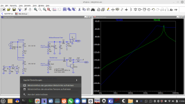
The simulation looks interesting - you can see that same peaking from the Audacity Frequency spectrum (as the resonant circuit boosts noise) taken when SAQ was not transmitting:-

Yes I agree with you - it was just interesting to try the design using a Triode, maybe a Pentode would be better.
"No, the losses of the coil, i.e. winding resistance, are the culprit"
When I was experimenting I tried 100K, 200K and 300K the Q did go up quite a bit from 100K to 300K.
It would also be interesting to forget about the Ferrite Rod and use a standard un-gapped Ferrite core, the number of turns to achieve resonance at 17200 Hz and with the 4n1 COG capacitor would be far less, giving a better Q. Reception would then rely on the antenna and earth connections.
The simulation looks interesting - you can see that same peaking from the Audacity Frequency spectrum (as the resonant circuit boosts noise) taken when SAQ was not transmitting:-
"It would also be interesting to forget about the Ferrite Rod and use a standard un-gapped Ferrite core, the number of turns to achieve resonance at 17200 Hz and with the 4n1 COG capacitor would be far less, giving a better Q. Reception would then rely on the antenna and earth connections."
It would help if you had a clue of electromagnetic fields. Per definition a coil with closed magnetic path does not receive any external field - i.e. is no antenna at all. Nonetheless you can use it in a filter circuit.
It would help if you had a clue of electromagnetic fields. Per definition a coil with closed magnetic path does not receive any external field - i.e. is no antenna at all. Nonetheless you can use it in a filter circuit.
Hold on I did say reception would then rely on the external antenna and a good earth. My experience with the Ferrite Rod was a weaker signal when compared with the Approx 10m length of external antenna.It would help if you had a clue of electromagnetic fields. Per definition a coil with closed magnetic path does not receive any external field - i.e. is no antenna at all. Nonetheless you can use it in a filter circuit.
I do understand that the closed un-gapped Ferrite core will receive nothing but it's the high Q at 17200 Hz that I am wanting.
On the occasion the Ferrite Rod was a bit of a pain because I didn't know which way to align it in 3 dimensions and I was very conscious of missing the transmission. So the external antenna picked up most of the signal and boosted the signal to noise ratio.
No pun intended. I just had to clarify.
The direction of the rod should be level and perpendicular to the direction of the transmitter.
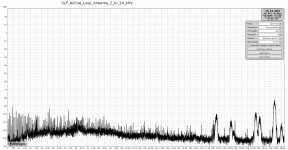
Meanwhile I extracted a very simple, aperiodic active loop antenna with constanst sensitivity in the range 10kHz~1MHz.
The direction of the rod should be level and perpendicular to the direction of the transmitter.
Meanwhile I extracted a very simple, aperiodic active loop antenna with constanst sensitivity in the range 10kHz~1MHz.
Attachments
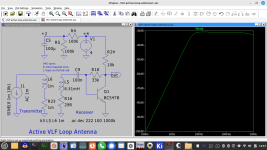
So L6 is your test input, L5 is 345 turns on a Ferrite Rod. The response is very flat from 10kHz to 1MHz ! Looks like a very clean and minimal design.
The bias on Q1 is the simplest way like was done years ago.
The bias on Q1 is the simplest way like was done years ago.
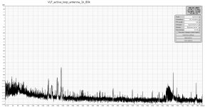
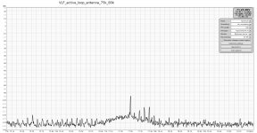
I build a quick and dirty setup. Ferrite coil, pre-amp feeding line-in of usb-soundcard Motu M4 with 192kHz sample rate. Connected to laptop with REW. And that's all. S/N is better than anything I tested before.
Attachments
Explorer E202 - VLF Receiver for a beginner -- http://www.vlf.it/romero2/explorer-e202.html
This one is a portable receiver intended for a beginner but I think most people would find it an interesting read.
Radio signals of natural origin are a fascinating subject. The first time I read an article I was bewitched by it: Beyond well known TV and Radio emissions there are some "on air" natural radio signals that really make the sky bigger. But here appears a problem: how to hear them if there are no receivers to buy? And looking for a simple and effective project to build at home, the response on mailing lists is always the same: "There are many schematics on the Internet...., look there" And then you feel confused: which will work best? Can I use my PC? How can I assemble a system to find and process natural radio signals most effectively?
If you are looking for a small receiver, simple to build, which runs on batteries, which works with a small antenna, which works with headphones, which also provides a good signal for PC analysis... the Explorer E202 meets all these needs.
Since this project is meant for beginners there are also included in the article some basic concepts: they are also mentioned in other articles on the site so If you already know these things just jump to the next paragraph. -Romero-
The unit works with a 75cm field probe called a stylus. It needs to be hand held or earth grounded. It also can work with a long wire. I am wondering: can it be adapted to an indoor unit but there is no mention of a using a ferrite core.
The text says TL071 but the schematic says TL081 which gives it a high-impedance FET input with a gain of 30. It has a line output for recording. It has an LM386 headphone driver. Fortunately, the LM386 is not necessary in my view.

- Home
- Amplifiers
- Solid State
- Tuned Sound Amplifier/Receiver for the VLF Christmas Eve transmission from SAQ, Grimeton, Sweden