I don't expect to see VLF at my location
Surely you will have VLF - it seems to get everywhere.
I'm afraid that I forgot a lot about antenna theory a long time ago. That said I think that a 10m diameter loop with say 64 turns would pick up a very strong VLF signal.The principle of wideband loop antennas is based on a "lowest possible" Z(in) of the amplifier, and lowest possible inductance of the loop at maximum area. For low impedance devices (common base etc.) that makes single turn loops mandatory for best results
Everything received everywhere ... that is the problem. Add to that the electronic noise in cities.Surely you will have VLF - it seems to get everywhere.
You are missing the way an audion works. At first It is an imperfect rf amplifier. Imperfect by its non-linear transfer characteristic. The non-linearity - or call it asymmetric behaviour - demolutes amplitude modulation in a way similar to a diode. That is why you will find no diode in the hole circuit. Next step is a tunable feedback - or regeneration. The cathode current flowing through part of the receive coil makes an oscillator circuit - that may or may not oscillate - depending on forward transconductance of the tube. By varying grid2-voltage the internal gain of the tube is set. By increasing the gain, more feedback un-dampens the circuit, thus increasing q-factor, circuit impedance and sensitiy as well. Crossing critical feedback the hole thing will oscillate at the resonanant frequeny of the input circuit - and due to nonlinear transfer characteristics - the oscillation modulates input signal and produces additional signals of the difference frequency - that are audible. This is a well known technique to make cw-modulated morse code audible since the beginning of radio transmissions.Regeneration for receivers was an awful wild idea, it's like saying the howl (microphony) of an older design Public Address system is useful.
I think you are doing fine.Yes, I should not be critical of other people's designs.
When I saw the post about the TV oscillator, I thought there must be a bug in the web software causing threads to be scrambled.
Yes but SAQ has no bandwidth just CW so you can apply a very sharp resonance/bandpass filters at the SAQ frequency, the other VLF signals are narrow band so again resonance and filtering. I live in Cardiff, not as big a city as Toronto. By far the worst noise problem I see on VLF is global lightning storms.Everything received everywhere ... that is the problem. Add to that the electronic noise in cities
Aridace,
Have you tried a regenerative loop? It seems like regeneration is making a comeback in the Ham homebrew world and being applied to everything. This NASA paper on Regen loops for VLF seems to turn up frequently.
https://ntrs.nasa.gov/citations/19940020710
I haven't read it - just put here as a maybe it's useful.
Win W5JAG
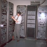
I found vintage photos of the Pinetree troposphere site which was setup on a mountain near my home town of Stephenville, N.L. after WWII. The photos were hosted by Military Communications and Electronics Museum. I got permission to copy them before it shut down. The photos were taken in 1959 when Queen Elizabeth and Prince Philip drove through town.That's interesting! Did you ever come across a number 19 set left over from WWII?
Yes tubes obsolete, but ceramic and metal tubes still used examples would be large high power water cooled transmitter tubes and of course the Magnetron in microwave ovens.
The station had various antennas and domes. It was maintained by the US Air Force. I laughed when watching some original Star Trek shows. I know where they got their knobs and switches from old military gear.
Attachments

Just as a further FYI, at least in the U.S. there is the 2200 meter ham band, 136-138 KHz, where it is legal to transmit and the lowFERS hang out.
Win W5JAG
Win W5JAG
OK but what I said wasYou are missing the way an audion works. At first It is an imperfect rf amplifier. Imperfect by its non-linear transfer characteristic. The non-linearity - or call it asymmetric behaviour - demolutes amplitude modulation in a way similar to a diode
"Ah maybe not, well not without modifying it somewhat. I'm not too up on valves but I think the regeneration causes oscillation and to render Morse code audible the oscillation is different from the CW frequency so the resonant circuit is always detuned slightly from the CW frequency"
Don't forget I'm thinking about this circuit as regards rendering Morse code from SAQ audible. Now there is no amplitude modulation as in speech AM only the presence or absence of carrier. The only way to render a carrier audible is to beat it with another slightly different local oscillator frequency and that arises from the regeneration. Now it follows that if the circuit is oscillating then it's gain is greatest at the oscillation frequency, therefore it's gain at the carrier frequency is somewhat less. This has to be true.
Also the common and clean way to make CW Morse code audible is to have a BFO (beat frequency oscillator) that the operator can adjust and that has no effect on the gain at the carrier frequency rather just mixes with it to produce the audible frequency which is the beat frequency.
Take your point as regards established practice over many years but with the benefit of hindsight with modern electronics and computing in mind and without meaning to blow my own trumpet I would rip a whole load of long established practices and designs to shreds.
Looks like about half of those racks are SP-600's. I have a mil variant, R-274C, here at my office. I think they made a VLF version of the radio The big kahuna LF / VLF radio of that era was likely the R-389, the VLF variant of the Collins R-390.I found vintage photos of the Pinetree troposphere site which was setup on a mountain near my home town of Stephenville, N.L. after WWII. The photos were hosted by Military Communications and Electronics Museum. I got permission to copy them before it shut down. The photos were taken in 1959 when Queen Elizabeth and Prince Philip drove through town.
The station had various antennas and domes. It was maintained by the US Air Force. I laughed when watching some original Star Trek shows. I know where they got their knobs and switches from old military gear.
Win W5JAG
Rich -
Why have a cathode resistor to spoil the gain? The pentode input gets its positive feedback via the cathode driving into the tap on the inductor, which in turn drives into the grid. The regen control varies the pentode screen voltage - more screen voltage, more plate current, more gain, more feedback. However, it looks like you'd have to have a pair of 600 ohm cans or a crystal earpiece to get any usable volume from the output. It's really an elegant, minimal parts count design. I may end up building it, as I have a few 6U8s floating around, and I bought a TV horizontal oscillator tuning coil years ago with this receiver circuit in mind. I also have a 125V power XFMR with requisite 6.3V filament winding. I may have to scour around to find a 50k pot with sufficient power rating (2W will probably do the trick, given the lowish plate voltage supply).
Given my predilection for powering circuits like this with a DC-DC converter driven by a SMPS adapter, I may go that route, as I have a DC-DC design already made up that has the filament and B+ outputs intended for a headphone amp design using the 13DR7 dual triode. I would just wind the transformer on the DC-DC to take 12V input from an appropriate switching adapter to generate 125V B+ and 6.3V filament outputs.
Last edited:
@fubar3 @w5jag That's a great photo, great to see equipment like that.I found vintage photos of the Pinetree troposphere site which was setup on a mountain near my home town of Stephenville, N.L. after WWII.
The number 19 set was iconic, so many were made. In the 1960's many of them were for sale in the UK as Army surplus. A great many of them were manufactured in Canada.
Before you rip it, try to really understand. I think some of the old principles can be used with modern parts.I would rip a whole load of long established practices and designs to shreds.
@bucks bunny @w5jag @fubar3
OK having given consideration to the valid points made by each of you I have modified the VLF Tube Receiver (intended for SAQ Grimeton) as follows:-

The 300K resistor is connected to 0V so as to fix the Q of the Ferrite Rod resonant circuit. Might be a good idea not to actually connect any antenna to the antenna terminal so as to protect the EC31 tube and the OPA891 OpAmp !!
Also the OPA891 may well have a rather high input offset current for this application but it sure is fast and high open loop gain - intended for professional audio applications. Output at the O/P terminal is carrier wave. Typically 17200 Hz.
OK having given consideration to the valid points made by each of you I have modified the VLF Tube Receiver (intended for SAQ Grimeton) as follows:-
The 300K resistor is connected to 0V so as to fix the Q of the Ferrite Rod resonant circuit. Might be a good idea not to actually connect any antenna to the antenna terminal so as to protect the EC31 tube and the OPA891 OpAmp !!
Also the OPA891 may well have a rather high input offset current for this application but it sure is fast and high open loop gain - intended for professional audio applications. Output at the O/P terminal is carrier wave. Typically 17200 Hz.
As regards regenerative circuits this little zinger the ZN414 would in its day likely be the pinnacle of regenerative possibilities:-

Only snag is that it won't work at VLF frequencies.
Only snag is that it won't work at VLF frequencies.
The 1st time I read about WB loops was during the early 1970s, in a German electronics magazine. I thought it was interesting to give it a try and as part of my job was suggesting graduation / "year of practice" projects, a candidate was interested and did a good job re report for university. So it (simplified version) got published (Elektuur / Elektor). It concerned an asymmetric amp with 0.7m diameter loop and worked so well that none of the builders complained. But it was meant for 0.5 - 30 MHz only, not VLF. Likewise my present loop, with higher performance so that the difference between night time and daytime EMI is clearly visible. The required setup for that allows non-optimal but acceptable use for VLF.I'm afraid that I forgot a lot about antenna theory a long time ago. That said I think that a 10m diameter loop with say 64 turns would pick up a very strong VLF signal.
See above post #297 - have connected the 300K resistor to 0V as it originally should have been.Why have a cathode resistor to spoil the gain?
- Home
- Amplifiers
- Solid State
- Tuned Sound Amplifier/Receiver for the VLF Christmas Eve transmission from SAQ, Grimeton, Sweden