Glass tubes make lousy coffee warmers - the mug always slides off ....
I say go for the metal 6V6's.
Win W5JAG
I say go for the metal 6V6's.
Win W5JAG
6L6GA's or metal 6V6's for breakfast?
To my girlfriends annoyance the kitchen table is currently decorated with a mix of 6080's, boxes of resistors and a drill.
Your test bench looks like my desk and kitchen table🙄
This was my kitchen table Friday ... and the second picture is this afternoon ... $600 worth of Mouser order later ... 😀
Attachments
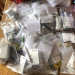
To my girlfriends annoyance the kitchen table is currently decorated with a mix of 6080's.......This was my kitchen table Friday...
I don't think I have ever had electronics stuff on the kitchen table, but maybe I did and don't remember......My best test of my wife's patience was building an automobile engine, and rebuilding the transaxle in the middle of the living room floor. This was a project that took about 3 weeks and we had a teenage daughter at the time. All of the parts were either new, or thoroughly cleaned so there was no serious mess, but the house was a serious obstacle course for a while. The new carpet was already ordered and scheduled for after the engine was done.
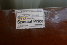
For now, all my messes are confined to the basement.....but I found something I couldn't resist and Sherri is not amused. We were out thrift store shopping with our daughter when I found a nice looking Hammond M3 tonewheel organ from 1958. The price was $39.95 and it plays perfectly.....it just weighs 249 pounds. Not quite sure how to get that down the basement stairs without killing myself, so it currently sits in the living room.......
Picture 1 and 2
...$600 worth of Mouser order later .....
My Mouser orders are limited to absolute necessities right now due to budget constraints, but I'm going to build some amps, good amps, with these boards. The question I have been running through my brain for the last few weeks is "just what do I build first." All construction must be done with minimum expenditure, which means no new transformers or other expensive things.
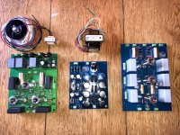
I have a shiny enclosure from Landfall Systems that was going to be a sweep tube amp before I left Florida, but never got built. Since then the world's supply of cheap 13GB5's vanished, so that choice went away. I made a picture of a mock up of how that amp was going to be built. The boards in that picture are the early version of this board.
Pictures 3 and 4
Choice #1 was to build an amp in that box with the big Edcor's using sweep tubes, or common audio tubes.
Choice #2 was to rebuild my 300Beast, a push pull amp that used 300B tubes. I have several Sovtek and Chinese 300B's and a bunch of 307A's that will run in that amp. I built it about 15 years ago with all junk box parts. $16 OPT's that were designed for guitar amps, photoflash electrolytics and a dumpster toroid for the power supply, and cheap components on a home made PC board for the driver. There was some kind of symbiotic unity among the cheap parts because that amp sounded fantastic to everyone who heard it. It also defied any attempt to upgrade it with decent parts. Anything I did mad it sound worse. We tried several $$$ OPT's and they just made it sound ugly, so it remained an ugly looking cheap amp for several years until it blew a fuse. I stuck a no-blo fuse in it and was rewarded with the stink of electrolytic goo. The amp has followed me to the basement.....but a few parts are missing. I still want to rebuild it using these driver boards, maybe with 307A's instead of 300B's.
This morning's find, and subsequent testing has all but made that decision for me. Amp #1 will be a triode mode 6550A / KT88 amp with the big Edcor OPT's in the Landfall box. I need to work out the power supply details. I need 500 to 525 volts of B+, +/- 150 volts to feed the mosfets and CCS on the driver board, and 8.8 amps of 6.3 volts to warm the tubes. The main power transformer will probably be a toroid in order to fit in the box. I have some surplus units, and some Anteks to test out.
I have some NOS JAN GE 6550A's but they are worth some serious $$$$, so I have been hesitant to use them in a project. Wednesday I found a box of Russian tubes and opened it looking for some Electro Harmonix KT88's that I bought about 10 years ago. That box didn't have the KT88's, but did have 6 twenty year old Sovtek 6550WA's, which went into the amp and made music for two days. I kept flipping between pentode and triode trying to decide which I liked best. This morning I unhooked the speakers and made some measurements. The Sovteks would make about 65 watts in triode on 500 volts, and 95 watts in pentode. I didn't want to push the old tubes beyond 500 volts.
Around lunch time I cracked open a box that was marked 307A (I got to hear them with these boards). The box did contain mostly 307A's, but there was a bunch of other tubes that I had been looking for. There were 7 X EH KT88, one EH6550, and a pair of Svetlana 6550's. Among the EH KT88's were a matched pair, and a matched quad......guess what went into the amp?
The test results for EH KT88's in triode with a 3300 ohm OPT, 525 Volts B+, 45 mA idle current:
power THD
0.1 W 0.186%
0.5 W 0.165%
1.0 W 0.206%
2.0 W 0.280%
5.0 W 0.450%
10 W 0.685%
20 W 1.082%
50 W 1.651%
70 W 1.886%
80 W 2.768%
90 W 4.96%
Attachments
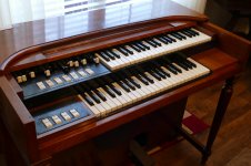
Nice organ George!
Speaking of cold, those Russian tubes have to be able to take this!
News - Town thermometer breaks in 'world's coldest village' at -89F - The Weather Network
Speaking of cold, those Russian tubes have to be able to take this!
News - Town thermometer breaks in 'world's coldest village' at -89F - The Weather Network
SO, I decided to build a KT88 / 6550 amp in a Landfall box. The amp works nice, but all those bench supplies won't fir into the box. Time to make a power supply.
First experiment:
I dig out a toroid that looks like a good fit. I bought this thing at least 10 years ago, probably more, when they first appeared on the market.....I have serial #001. It cost me $100 at the time which I thought was outrageous, but I wanted to make a big (at the time) tube amp. That amp never got built, and those transformers now cost $280!
https://toroid.com/Portals/0/236.5072.pdf
The transformer has two separate 6.3V 5A heater windings, so I wired one to each channel.
There is a 720 VCT 750 mA winding, so I connected it up to a perf board rectifier circuit that I made years ago. Basically a FW rectifier made with a bunch of diodes in series and a cap bank made with a bunch of caps in series / parallel to give about 200 uF in the configuration used here.
I connected this directly to the amp's B+ input, and flipped the switch.....as expected it went hummmmmmmm. There was about 10 volts of 120 Hz on the output, but I wanted to measure DC voltages so I cranked it up. Clipping came at about 65 watts where the DC voltage was about 480 volts. Idle voltage was about 520 and power up voltage (before the tubes got hot) was 545 volts. Obviously I need a choke, but I can't find one.
I found this tiny little choke stolen from an HP audio oscillator. I have a bunch of them, so I hook one up. Idle B+ was about 490 volts. A full power attempt resulted in 40 watts at a B+ voltage of 400 volts and a bunch of smoke and stink from the choke.
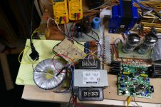
I remembered an old trick from when I was a kid making zero budget guitar amps. Find a power transformer with two 120 volt primary windings that's big enough to eat all the B+ supply current (600 mA ) and wire the two primaries in series with the power and ground wires from your rectifier / transformer / capacitor circuit like a common mode choke. I fetched a 500 VA industrial control transformer (overkill, but handy) and wired it into my simple power supply. Did it work?
Lets say I have NEVER build a BREADBOARD this quiet. I had to run around turning things off to get a reading on the background hum......It's nonexistent. The Walmart LED shop lights were filling the scope with tiny pulses around 24 KHz at the 9 mV level. With them and the LED ceiling lights off, the voltage at the speakers with the input disconnected it 700 MICROVOLTS, and that's HF noise, probably from the 65 inch TV in the room above me.
Previous distortion measurements showed low distortion at low power, but they were with regulated bench supplies. Now I have just a single capacitor on the low voltage supply that feeds the mosfets, and a CLC (the transformer) filter on the main B+. How would this perform in testing?
Maximum output power is obviously lower since the previous testing was done with a regulated 525 volt supply. The unregulated simple supply made 545 volts at power on, dropped to 510 at idle and 485 at 70 WPC (both channels driven).
As mentioned the background noise on the output is 700uV (0.7mV) the analyzer could not read its frequency, and the scope showed noise with some HF spikes. The distortion numbers could now be read down to 10 milliwatts where I couldn't go below 100 mW before.
power THD
0.01W 0.175%
0.1 W 0.139%
0.5 W 0.209%
1.0 W 0.253%
2.0 W 0.373%
5.0 W 0.585%
10 W 0.895%
20 W 1.487%
50 W 1.924%
60 W 1.996%
65 W 2.391%
70 W 4.28%
I have a 400 volt and a 360 volt Antek toroid. These are much cheaper, and technically 800 mA short on heater current. I may try the 360 volt version, but the 400 volt transformer may result in too much voltage unloaded and at idle.
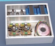
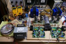
Picture #1 shows the crude and simple power supply.
The HV winding on the toroid feeds the perf board which has diodes and capacitors. Its output goes through the primary windings on the big GE transformer (silver and black). The purple wire is the negative output, and it goes to the ground terminal on the breadboard. The orange / white wire is the positive output and it goes to the B+ terminal on the breadboard.
The small transformer to the left of the meters ia a 50VA isolation transformer. It has a pair of 120 volt secondaries which are connected to 4 diodes and 2 capacitors on the green board to make +/- 160 volts. The common wire (grey) is connected to ground on the breadboard. The negative 160 volts (black) is connected to mosfet - on the breadboard, and the +160 volts (red) is connected to mosfet + on the breadboard. The meters are displaying the cathode currents in one channel at 65 WPC.
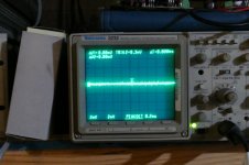
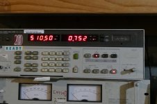
Picture #2 shows 752 microvolts of noise. The number randomly bounced around between 600 and 800 microvolts. The frequency display randomly showed anything from a few hundred Hz to 10 KHz.
Picture #3 shows the scope on its most sensitive setting across the speaker leads.
Picture #4 shows the expensive toroid.
First experiment:
I dig out a toroid that looks like a good fit. I bought this thing at least 10 years ago, probably more, when they first appeared on the market.....I have serial #001. It cost me $100 at the time which I thought was outrageous, but I wanted to make a big (at the time) tube amp. That amp never got built, and those transformers now cost $280!
https://toroid.com/Portals/0/236.5072.pdf
The transformer has two separate 6.3V 5A heater windings, so I wired one to each channel.
There is a 720 VCT 750 mA winding, so I connected it up to a perf board rectifier circuit that I made years ago. Basically a FW rectifier made with a bunch of diodes in series and a cap bank made with a bunch of caps in series / parallel to give about 200 uF in the configuration used here.
I connected this directly to the amp's B+ input, and flipped the switch.....as expected it went hummmmmmmm. There was about 10 volts of 120 Hz on the output, but I wanted to measure DC voltages so I cranked it up. Clipping came at about 65 watts where the DC voltage was about 480 volts. Idle voltage was about 520 and power up voltage (before the tubes got hot) was 545 volts. Obviously I need a choke, but I can't find one.
I found this tiny little choke stolen from an HP audio oscillator. I have a bunch of them, so I hook one up. Idle B+ was about 490 volts. A full power attempt resulted in 40 watts at a B+ voltage of 400 volts and a bunch of smoke and stink from the choke.
I remembered an old trick from when I was a kid making zero budget guitar amps. Find a power transformer with two 120 volt primary windings that's big enough to eat all the B+ supply current (600 mA ) and wire the two primaries in series with the power and ground wires from your rectifier / transformer / capacitor circuit like a common mode choke. I fetched a 500 VA industrial control transformer (overkill, but handy) and wired it into my simple power supply. Did it work?
Lets say I have NEVER build a BREADBOARD this quiet. I had to run around turning things off to get a reading on the background hum......It's nonexistent. The Walmart LED shop lights were filling the scope with tiny pulses around 24 KHz at the 9 mV level. With them and the LED ceiling lights off, the voltage at the speakers with the input disconnected it 700 MICROVOLTS, and that's HF noise, probably from the 65 inch TV in the room above me.
Previous distortion measurements showed low distortion at low power, but they were with regulated bench supplies. Now I have just a single capacitor on the low voltage supply that feeds the mosfets, and a CLC (the transformer) filter on the main B+. How would this perform in testing?
Maximum output power is obviously lower since the previous testing was done with a regulated 525 volt supply. The unregulated simple supply made 545 volts at power on, dropped to 510 at idle and 485 at 70 WPC (both channels driven).
As mentioned the background noise on the output is 700uV (0.7mV) the analyzer could not read its frequency, and the scope showed noise with some HF spikes. The distortion numbers could now be read down to 10 milliwatts where I couldn't go below 100 mW before.
power THD
0.01W 0.175%
0.1 W 0.139%
0.5 W 0.209%
1.0 W 0.253%
2.0 W 0.373%
5.0 W 0.585%
10 W 0.895%
20 W 1.487%
50 W 1.924%
60 W 1.996%
65 W 2.391%
70 W 4.28%
I have a 400 volt and a 360 volt Antek toroid. These are much cheaper, and technically 800 mA short on heater current. I may try the 360 volt version, but the 400 volt transformer may result in too much voltage unloaded and at idle.
Picture #1 shows the crude and simple power supply.
The HV winding on the toroid feeds the perf board which has diodes and capacitors. Its output goes through the primary windings on the big GE transformer (silver and black). The purple wire is the negative output, and it goes to the ground terminal on the breadboard. The orange / white wire is the positive output and it goes to the B+ terminal on the breadboard.
The small transformer to the left of the meters ia a 50VA isolation transformer. It has a pair of 120 volt secondaries which are connected to 4 diodes and 2 capacitors on the green board to make +/- 160 volts. The common wire (grey) is connected to ground on the breadboard. The negative 160 volts (black) is connected to mosfet - on the breadboard, and the +160 volts (red) is connected to mosfet + on the breadboard. The meters are displaying the cathode currents in one channel at 65 WPC.
Picture #2 shows 752 microvolts of noise. The number randomly bounced around between 600 and 800 microvolts. The frequency display randomly showed anything from a few hundred Hz to 10 KHz.
Picture #3 shows the scope on its most sensitive setting across the speaker leads.
Picture #4 shows the expensive toroid.
Attachments
This is exciting. I'm trying to understand what the power requirements will be for this amp.
Is there an Edcor Power Transformer that might meet the needs of this amp?
Or could you have them design one to meet your needs?
The xpwr-131 was designed for the TSE and it works great.
Is there a reason you are leaning toward toroids?
Is there an Edcor Power Transformer that might meet the needs of this amp?
Or could you have them design one to meet your needs?
The xpwr-131 was designed for the TSE and it works great.
Is there a reason you are leaning toward toroids?
I tried both Antek transformers. The Anteks that I have are the older versions without the shield between the primary and secondary. I'm not sure if the newer transformers will act any differently.
The AN-4T360 resulted in about 530 volts unloaded, but the B+ dropped to about 435 volts at full crank, which was about 50 WPC. The hum and noise was similar to the expensive transformer, maybe a bit higher, but still well below 1 mV. For $57 VS $280 I wouldn't hesitate to use it. It ran for about an hour and was no warmer than the expensive transformer.
The AN-4T400 resulted in 604 volts unloaded, and 545 volts at idle. With 45 mA of idle current, the idle dissipation is 24.5 watts, still lower than what I run my SSE at (435 volts 80 to 100 mA) which still has the original pair of identical EH KT88's in it. When the knob was turned up to the edge of clipping the B+ was 505 volts, making about 70 watts. The KT88's would probably live at this kind of voltage, but the same B+ feeds the driver board. There is a 500 volt cap downstream of a 10K resistor. The 6CG7's are "stacked" so that the first tube gets 100 to 150 volts, and the second eats the rest. That puts 400 volts on the second tube. They seem to like it, but for how long.
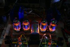
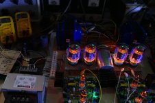
While the big Antek was powering this thing, I turned off the lights and took a few pictures. These EH KT88's are famous for the "blue on the glass" glow (good glow), but when have you ever seen a 6CG7 with blue on the glass?
I stuck the expensive transformer back in my amp, since I already have it and it is the best choice of what I have that will fit in the chassis.
There are some other choices that would be good, like the old Allied 6K7VG. I have built dozens of guitar amps with those power transformers and the old Sovtek 6550WA's. These or the Hammond 374BX (or 374BX) would be good for mono blocks
The industrial transformer makes an excellent choke, but weighs a ton and won't fit my chassis. I tried an Antek toroid, but it looses it's choking ability when you lean on the power. I need to find something else.
The AN-4T360 resulted in about 530 volts unloaded, but the B+ dropped to about 435 volts at full crank, which was about 50 WPC. The hum and noise was similar to the expensive transformer, maybe a bit higher, but still well below 1 mV. For $57 VS $280 I wouldn't hesitate to use it. It ran for about an hour and was no warmer than the expensive transformer.
The AN-4T400 resulted in 604 volts unloaded, and 545 volts at idle. With 45 mA of idle current, the idle dissipation is 24.5 watts, still lower than what I run my SSE at (435 volts 80 to 100 mA) which still has the original pair of identical EH KT88's in it. When the knob was turned up to the edge of clipping the B+ was 505 volts, making about 70 watts. The KT88's would probably live at this kind of voltage, but the same B+ feeds the driver board. There is a 500 volt cap downstream of a 10K resistor. The 6CG7's are "stacked" so that the first tube gets 100 to 150 volts, and the second eats the rest. That puts 400 volts on the second tube. They seem to like it, but for how long.
While the big Antek was powering this thing, I turned off the lights and took a few pictures. These EH KT88's are famous for the "blue on the glass" glow (good glow), but when have you ever seen a 6CG7 with blue on the glass?
I stuck the expensive transformer back in my amp, since I already have it and it is the best choice of what I have that will fit in the chassis.
There are some other choices that would be good, like the old Allied 6K7VG. I have built dozens of guitar amps with those power transformers and the old Sovtek 6550WA's. These or the Hammond 374BX (or 374BX) would be good for mono blocks
The industrial transformer makes an excellent choke, but weighs a ton and won't fit my chassis. I tried an Antek toroid, but it looses it's choking ability when you lean on the power. I need to find something else.
Attachments
Is there a reason you are leaning toward toroids?
The amp I'm going to build for myself needs to fit in a chassis that I already have. It will be used in a rack mount situation, so all the parts must go inside the box. The two big Edcor OPT's eat up mych of the space, so I need to find a smallish power transformer, preferably one I already have.
I'm sure that Edcor could cook up the ideal transformer, or may have something already designed. I haven't looked through the existing catalogs of Hammond or Edcor yet.
This is exciting. I'm trying to understand what the power requirements will be for this amp.
The power requirements for this, and any other amp depend on how much power output you want from it, and how you are going to use it. Assuming KT88 / 6550's in triode mode, a reasonable power output level would be 35 to maybe 70 watts per channel.
Assuming this amp design, it will take 8.8 amps at 6.3 volts to heat the tubes, 55 watts burned up as heat.
The driver board needs to be fed. It's all class A, so like the tube heaters, its mostly all turned into heat. The tubes want about 12 watts, and the mosfets maybe 8 watts. So before we have even powered up the KT88's, we have consumed 55 + 20, or 75 watts.
The output stage gets a bit trickier, since how much it needs, depends on how much power you want from it, and how you will use it. You must design and build the amp for the maximum expected power output, even if you never use all of it's capacity. A 70 WPC amp will need a higher B+ voltage, and will draw more current when cranked wide open, so a bigger power supply and OPT is needed compared to a 35 WPC amp, even if all other components are identical.
A push pull triode connected output stage typically operates at about 50% efficiency when driven to maximum power output. So our 70 WPC (140 watt total) output stage will need 280 watts of B+ power, while our 35 WPC output stage will need 140 watts of B+ power. Add these numbers to the 75 watts consumed by the tube heaters and driver board B+ and we get 215 to 355 watts of total power consumed by the amp.
Power transformers are rated in VA, not watts. There is some loss in the transformer, and these losses are exacerbated by the fact that our rectifiers only consume large amounts of power in short bursts 120 times a second (on 60Hz power). These are often incorrectly called power factor losses, by the term has become standard now since every PC power supply is now rated this way. The "power factor" on a non PFC power supply like those in tube amps is roughly 80%, which means our transformer needs to be 20% bigger than we calculate, so now we need a 258 to 426 VA power transformer. These are large and expensive.
This is the textbook approach to designing an amp, and many audiophiles and amp designers believe that it should be followed. This is indeed the case if we wanted to turn our amp up to full power with a continuous sine wave and leave it there for hours. This would be valid design criteria if our amp was to be used driving an industrial shaker table or some laser galvos (a 4 inch "voice coil"). Both of these have been solid state since the 1960's.
Music has a "crest factor" or in the cell phone RF amp world, we called it peak to average ratio. This means that for a 10dB crest factor our 70 WPC amp would be making 7 WPC, AVERAGED over time if it were cranked to the point of clipping on musical peaks. Even the most compressed boom boom dance music does better than 10dB. Most music runs in the 20dB range, so our 70 WPC amp will average around ONE WATT of power output when played very loudly with most music.
Bob Carver made his career by exploiting this fact. He made some very powerful solid state amps with tiny power transformers and minimal heat sinks. For the most part, they didn't blow up. I had one of the original Carver M-400 amps. despite the warnings that they were for listening to music under normal conditions only, not for sound reinforcement or musical instrument use, I played my guitar through it at wall shaking levels. After 10 minutes or so, it would just simply shut off.
So we can just build our power supply for ONE watt? No, Carver's amps were solid state with tons of feedback to kill any crossover distortion. We are building a tube amp, and we already have 75 watts consumed without considering the output tubes. We could set our output tubes up with very little bias (class B) and apply a ton of feedback, and probably build an amp that sounded very much like a solid state amp, but why? Just build a solid state amp....it's cheaper.
We will set our amp up in class AB with a fairly high idle current such that the amp operates in class A for most of the time, and transitions to class AB on transient peaks. Remember an amplifier, any amplifier has ZERO efficiency when it produces zero power. Just as your car turns gasoline into heat at idle, a HiFi amp turns electricity into heat at idle, neither produces any useful output, and the efficiency is zero. If you increased the idle RPM of your car, it would require more fuel to do nothing. Our amp will burn more energy with a higher idle current, doing nothing, but the car, and the HiFi amp will make the transition from nothing to very low output smoother if the idle consumption is raised.
The size of our power supply, and the output tubes in most tube amps is really determined by how much energy we want to burn up at idle to make this transition smoothly. The extreme case is a full Class A amplifier where there is no transition. The tube current is the same, from idle to full power. Those power supply numbers quoted above, would be bare minimum for a full class A amp at the 35 WPC and 70 WPC power levels. A class A amp using KT88's or 6550's would need 4 tubes per channel at 35 WPC, and 6 or 8 at 70 WPC.
The power supply, OPT and the number or size of the output tubes, is a big tradeoff between these two extremes, with most amplifiers somewhere near the middle.
My amplifier is designed for a rather high maximum power output for KT88's in triode, 65 WPC. There are limited ways to get this much power. One could use a 3300 ohm OPT and nearly 500 volts of B+, or a 5,000 ohm OPT and somewhere over 600 volts, which is really too much for these tubes in triode. I already had the OPT's so my choice was made.....figure out how much power I could get with a power transformer that I already had. With the combination of parts in the amp today, it stays "technically" in Class A to about 8 watts. This means that both output tubes are conducting current for ALL of an audio cycle. It does NOT mean the the "off" tube remains linear for the time it is still conducting. It stays linear (cathode current is a sine wave) up to about 1.5 watts. These numbers would be higher with a 5000 ohm or higher OPT, at the expense of maximum power output capability.
If you haven't ordered OPT's or power transformers yet, you have the maximum flexibility in picking parts. The first step is to determine how many watts you need (or want) at full power. Do you listen to loud music at high volumes through inefficient speakers, or have more moderate listening requirements. This will determine how much of that power you will use most of the time.
I had already purchased the 3300 ohm Edcors several years ago. I had built some sweep tube amps in the 125 WPC range, and that's what I was going to build with those transformers and the Landfall chassis. I have decided to build a BIGGER amp with the TV sweep tubes, so the logical choice with these parts is a triode KT88 amp.
I have found a combination of low cost chokes that will work in this design. I had two of them, so I ordered one more. The power transformer that I have also has a pair of 50 volt taps, which are not quite enopugh voltage for the mosfet supply, but could work with a voltage doubler in the power supply. That would likely make the power supply design a "one off" so I plan to continue looking at a small PC board transformer for the mosfet supply. These were ordered as well.
That is a seriously nice chassis.
Did you perforate that cover in the PA section, or do they do that for you?
Win W5JAG
Did you perforate that cover in the PA section, or do they do that for you?
Win W5JAG
T
If you haven't ordered OPT's or power transformers yet, you have the maximum flexibility in picking parts. The first step is to determine how many watts you need (or want) at full power. Do you listen to loud music at high volumes through inefficient speakers, or have more moderate listening requirements. This will determine how much of that power you will use most of the time.
.
I for one am looking for more power than my EL84 SPP can currently deliver to drive my AR3a speakers. Occasionally I need to crank it up to "11". The amp sounds great, but I assume it must be distorting, even though I can't hear it.
I recall that the SPP can deliver 15 watts, I don't know where I got that from, but you know better than I do.
So let's say I'm looking for twice the power. 35 to 50 watts sounds like a lot to me. Jazz, Classical, and folk are what I listen to the most.
That being said I'm looking to build the best sounding amp I can with your boards, power is secondary. I have yet to decide on whether to build monoblocks or a stereo amp.
I have not purchased a power transformer or output transformers yet.
I'm assuming that I cannot reuse the 25 watt 7.6K ohm Edcor output transformers that are in the SPP and that I will need to purchased ones that are rated for 50 watts and that are in the 3.3 to 5K range.
Thank you for the thoughtful lesson on power requirements. I think I get about half of what you said. I did take physics in college, but ended up a theater/English major.
take care, Jacques
Did you perforate that cover in the PA section, or do they do that for you?
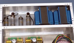
That chassis is exactly as received from Landfall. They had several options at to how it could be made, and I asked if the rear section could be perforated for airflow. That's what I got. All the aluminum is 1/8 inch thick for those monster OPT's.
I just wished that they could build one big enough for a 500 WPC sweep tube amp.
The power requirements for this, and any other amp depend on how much power output you want from it, and how you are going to use it. Assuming KT88 / 6550's in triode mode, a reasonable power output level would be 35 to maybe 70 watts per channel.
...
Impresive lecture 🙂
It is, but it won't last. I put a pair of the same tubes into my SSE amp and the blue glow faded within a few months, and was totally gone within a year.
Yeah, I kinda got carried away with the theoretical explanation and never got to the real part. I usually stick a bench power supply on the amp, and crank it while watching the meter. My amp draws 600 mA on 500 volts at full tilt sine wave into 8 ohm resistors. Playing real music into speakers will of course make the current meter dance all over the place, but a big fat cap after the meter will calm it enough that you can get a good estimate of the AVERAGE current, since that's what the TRANSFORMER needs to supply. The rectifier needs to be rated for the full current plus some margin.
My amp draws about 200 mA while playing loud music with the scope showing occasional clipping on transients. It will eat about 300 mA if turned up to the point of obnoxious distortion. Since I won't play it that way for more than a few seconds, a 300 mA power transformer should be sufficient.
The choke lies somewhere in between since it's ability to act as a choke disappears if core saturation is reached. I decided that I would use 3 chokes, a pair of Triad C-17X (1.5H, 300 mA), one for each channel, and a C-7X (10H, 90 mA) for the driver board. They were ordered Sunday, but Mouser hasn't shipped them yet. I will probably use a mosfet "regulator" for feeding the driver board a constant supply voltage.
Impresive lecture 🙂
Yeah, I kinda got carried away with the theoretical explanation and never got to the real part. I usually stick a bench power supply on the amp, and crank it while watching the meter. My amp draws 600 mA on 500 volts at full tilt sine wave into 8 ohm resistors. Playing real music into speakers will of course make the current meter dance all over the place, but a big fat cap after the meter will calm it enough that you can get a good estimate of the AVERAGE current, since that's what the TRANSFORMER needs to supply. The rectifier needs to be rated for the full current plus some margin.
My amp draws about 200 mA while playing loud music with the scope showing occasional clipping on transients. It will eat about 300 mA if turned up to the point of obnoxious distortion. Since I won't play it that way for more than a few seconds, a 300 mA power transformer should be sufficient.
The choke lies somewhere in between since it's ability to act as a choke disappears if core saturation is reached. I decided that I would use 3 chokes, a pair of Triad C-17X (1.5H, 300 mA), one for each channel, and a C-7X (10H, 90 mA) for the driver board. They were ordered Sunday, but Mouser hasn't shipped them yet. I will probably use a mosfet "regulator" for feeding the driver board a constant supply voltage.
So do you know why the glow disappears?
The blue glow is caused by stray electrons hitting the glass at high velocity causing some impurities in the glass to phosphoresce. It has been stated that the deep blue comes from Cobalt. The two main theories as to why the blue fades is that the Cobalt looses some of its phosphorescence over time, possibly due to the electron bombardment. It has also been stated that the vacuum degrades over time, and the resulting gas captures (ionizes) the stray electrons, or slows them down enough that they are attracted to the plate instead of zipping through the holes and hitting the glass.
I tend to believe the second theory. The glow seems to be related to the voltage applied to the tube's plate, and not the current. This would cause the higher electron velocity. The images on the glass are sharply defined now (NOS tubes) but will get fuzzier as they fade.
Unfortunately, I managed to kill one of these KT88's due to a stupid mistake caused by too many clip leads being used in my breadboard test amp. The plate supply became disconnected while testing at high power in pentode mode. This caused instantaneous meltdown of the screen grid in one tube, and a blown cathode resistor in the other. I don't plan on powering the amp up again until my first cut at a real power supply gets finished. Then I will use the Chinese tubes for initial testing.
- Home
- More Vendors...
- Tubelab
- Tubelab Universal Driver Board, 2015 version