Thanks George.
I'm testing a bunch of used 6CG7s and 6GU7s (Mu 17) to see what I might have to work with, or if I need to buy some more tubes.
I also have a few 12AT7s and some others that might serve as the first stage along with the lower Mu 6GU7s in the driver position. The problem with that would be heater operation.
Well it was short lived. When I turned the unit back on nothing. DRV 1 and 2 now sit at the full negative supply voltage. R37 and 43 make a small difference. Maybe the mosfets are toast. I was checking the temperature when the amp was running and they were not getting too hot.
the most time consuming part...making the two chassis.
That's where my amp project is temporarily stalled, and I only have one chassis to make.
I am not sure how much bias current to let flow. I set 35mA as a start
The data sheet gives 50 mA per tube as typical. If you have distortion measurement capability set the output power to somewhere between 1 and 5 watts and slowly increase the bias to the point where the distortion stops dropping. It's usually lower than the data sheet typical.
The problem with that would be heater operation.
All three possible heater pins are brought out to the connectors, so the use of 12 Volt center tapped heaters is possible, but mixing them in the same amp would require some hacking of the PCB runners. I have use a 5751 in the first stage and a 12BH7 or 5965 in the second stage, and I have used a 6BQ7 or 6DJ8 with the 6CG7. Both combinations provide a little more gain for making large drive voltages, or piling on the negative feedback.
Maybe the mosfets are toast.
Mosfets usually fail to a short. This would put the full positive supply on the outputs. Check that your +165 supply is still alive. The mosfets do dissipate about 2 watts each and should have a heat sink of some type on them. I plan on just screwing them to the chassis.
It may also be wise to pull the output tubes while messing around with the board. I have a fried KT88 because I knocked the plate supply plug out with the screen still powered. The grid wires lit up the room for about 2 seconds.
All the supplies seem to be working. I have a few household things to attend to and then I can try troubleshooting
Got a pass on housework. Off to the basement to try and figure this out
My plan is to put the last few parts into my second driver board so I have something to compare to
The second board works and I believe I see the problem with the first board and I feel kind of clumsy. I hadn't trimmed the leads of IC 3 and 4 and they had been bent over and were shorting out. I'll check if this was really the problem tomorrow.
I do notice that when the volume is turned up a bit that there is a nasty crackling sound. It mostly goes away when I have the volt meter hooked to the cathode resistors to check bias. The bias adjustment is very touchy. Perhaps the amp is oscillating. I can look at it with my oscilloscope running into a dummy load tomorrow. I used no grid stopper resistors. Also possibly of note the whole circuit is floating. I did not hook up the earth wire from the power inlet.
All will have to wait until tomorrow. I'm done for today...It's well past beer:30
Evan
I guess it's been one of those days. I have been working on a totally new concept off and on for several years. There have been a few small experiments, but for the most part it has only existed in the mind of the circuit simulator.
I built up the first test board of the new circuit, and preliminary testing looked very good. I was attempting to plot some curves that were well beyond the range of the curve tracer when the whole mess exploded. A 650 volt 1.7 amp power supply with 1000 uF across its output will do that.
There were a few parts that just vanished leaving only a black stain on the perf board. One mosfet is split in half with two pins on one half, and one on the other. I'm sure the tube is dead, and one cheap Harbor Freight multimeter got blasted.
One of the parts that vanished was a zener diode, my last of of that kind, so no more fun till Mouser can get me new ones. I think I need bigger mosfets too.
As long as you still have all your fingers and both your eyes all’s good. Bigger mosfets mean bigger bang?
Bigger mosfets mean bigger bang?
Hopefully not. I have a newer more modern power supply that I haven't used yet, primarily because it means moving that 70 pound monster that's on the shelf now. The newer digital SMPS should have faster current limiting. No power supply at the 600+ volt level is quick enough to save the silicon from blowing, but it should reduce the shrapnel.
I hadn't trimmed the leads of IC 3 and 4 and they had been bent over and were shorting out.
That would explain loss of sound, but shouldn't affect the mosfet bias circuit. Check to see if the voltage at the wiper of the bias pots are actually changing. If not, it could be bad mosfets. The mosfets contain internal zener diodes to protect the gates from ESD or other excessive voltages. I have seen these short out which will cause your symptoms.
The bias adjustment is very touchy. Perhaps the amp is oscillating.
If the bias suddenly "snaps" or jumps from one current level to another it is possibly oscillation. It was an oscillation that caused the shorted zeners in the mosfets in amp built with these driver boards too.
I have not seen oscillation in amps built using these boards except when using high Gm TV sweep tubes. I don't remember any unusual effects when testing the 4D32's but I typically employ all sorts of oscillation suppression stuff that I have learned over the years. The 4D32 IS a transmitting tube, optimized for RF, so it will go there if conditions exist.
The wire connections from the driver board to the tubes should be as short as possible. There should be a short heavy wire from the 4D32 cathode directly to one of the ground pins on the driver board. This may be the 1 ohm sense resistor leads. I typically run it to the B++ or MOS ground pin. The wires from the driver board to the 4D32 grid pins should also be short. I typically use a low value (10 to 100 ohm) resistor with ferrite beads on it's leads.
A tube can oscillate if its grid and plate connections have enough inductance to cause an RF resonance. It WILL oscillate if either grid (G1 or G2) leads and the plate or cathode leads resonate at similar frequencies, or related harmonic frequencies. Short fat wires have lower inductance moving these resonances up out of the tubes operating frequency range. Added resistance lowers the resonant peak ("Q") and helps prevent oscillation. Some tubes like the 807 and 6146 require a plate damper to kill oscillation. These were made by winding 10 or so turns of wire around a 100 ohm carbon composition resistor, connected in parallel with the resistor. This is inserted in series with the plate lead right at the plate cap. I have gotten by by slipping a few large ferrite beads over the plate cap wire.
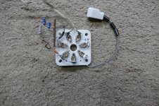
Here is the picture of my 4D32 socket and plate cap as wired for a temporary experiment. That short black wire went directly to the driver board. The terminal strip was added later for a dual drive experiment where the board fed G1 and G2. It didn't work out. I probably had beads on the G2 wiring as well.
Attachments
Thanks for the pointers. As it stands now the wires from the driver board to the output sockets are quite long. I’ll spend some time and neaten things up. I had the amp playing this morning with 1k grid stoppers and it seems to be working. I have my oscope and a signal generator set up as well as an 8 ohm dummy load. I’ll snap a few pictures of it running
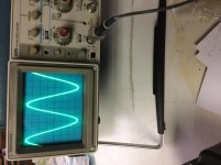
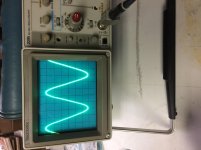
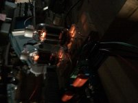
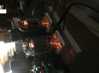
Ok. Neatened up / shortened the wiring. Used 11 ohm grid stoppers and the amp seems to work great. I let it play for about an hour and then took these photos. 10:1 probe 8 ohm load. Note volts/division in the second photo. Oh my...
Ok. Neatened up / shortened the wiring. Used 11 ohm grid stoppers and the amp seems to work great. I let it play for about an hour and then took these photos. 10:1 probe 8 ohm load. Note volts/division in the second photo. Oh my...
Attachments
Tubelab_com said:.... To get +/-150 volts, you need two windings. A simple half wave rectifier with one end of the single winding grounded will indeed make +/- 150 volts, but the currents drawn must be equal or the transformer will not be happy. This is especially true with a toroid. The negative supply has about 20 mA extra drawn from it. .....
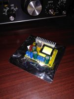
Could the DC-DC converters that are ubiquitous these days be useful here?
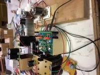
Some have only a positive output, some have positive and negative output, the cost difference is insignificant. I used the one in the picture to supply the entire B+ to the push pull mule. I haven't used the negative output, and don't know if unbalanced current would be a disaster or not. If they work, as cheap as they are, a second module could be used for the negative rail. These are ( were? ) about $6 delivered.
The one in the picture is sensitive to the quality of the low voltage DC input, in a way that I am so far unable to define. It works fine with some low voltage transformers, won't work at all with others for no apparent reason.
I planned on ( edit: trying to ) make a power supply with these, but it's several projects down.
Win W5JAG
Attachments
Last edited:
In theory they could be useful, but they would be used to supply the negative bias that keeps things from melting. I would be hesitant to trust expensive tubes and transformers to a cheap module when the isolation transformer is $15 and the associated caps, resistors, and diodes are under $10.
I have already blown up two of these little modules, but neither were the same ones that you show in the picture.
I have been abusing a simple 4 diode bridge and two caps on a N-68X for years without issue. It has survived more than a few momentary shorted outputs.
I have already blown up two of these little modules, but neither were the same ones that you show in the picture.
I have been abusing a simple 4 diode bridge and two caps on a N-68X for years without issue. It has survived more than a few momentary shorted outputs.
What are the caps and diodes you are using with the N-68X for the mosfet supply? I am assuming that the same ones could be used for mono-blocks?
I used 4 X UF4007 diodes because I had them. 1N4007's will also work as will the lower voltage versions. I would use something rated for 400 volts or more.
I used some 330 uF 400 volt electrolytics, again because I had them. I try to use caps rated for use at 105 degrees C in a tube amp, because tube amps make heat and caps hate heat. Anything over 250 volts is OK.
Any 1 to 3 amp diode that's good for 400 volts or more will work. The cap values are not critical either. Up to a point bigger is better, but the total current draw on these supplies is only about 50 mA. There will be brief transient current peaks on the positive 165 volt supply when the grids are driven well above 0 volts, but these should be brief and only when the amp is run near or at clipping. Use your best or largest cap on the positive supply.
My version was just 4 diodes and two caps. I put it together as a test board with intentions of building something better, but testing reveals no hum or distortion in the breadboarded amp. I still think I will go for a CRC or CLC supply in the final build using 100 uF for the first cap and 220 uF or 330 uF for the second cap. Again I'm choosing these values because I have them annd my amp is size constrained.
If I use chokes they will have to be small. A pair of resistors in the 220 to 470 ohm range will work, and may be what I use. The resistors should be 2 watts or more just to handle the cap charging surge on power up.
As evanc has demonstrated BIG caps will work too, but not for my project.
Miniaturization is not my specialty.
I’m looking into software based distortion measurement so I can tune this amp properly. Any suggestions would be welcome.
I’m looking into software based distortion measurement so I can tune this amp properly. Any suggestions would be welcome.
I’ve used these for the mosfet supply in my amps as well as a few solid state builds. They need a clamp on heat sink
http://ixapps.ixys.com/datasheet/fbe22-06n1.pdf
R2A-CT6-38E Ohmite | Fans, Thermal Management | DigiKey
http://ixapps.ixys.com/datasheet/fbe22-06n1.pdf
R2A-CT6-38E Ohmite | Fans, Thermal Management | DigiKey
Got both channels working. My klutzy move had taken out the mosfets. Even with the spaghetti madness wiring on my bench the amps are very quiet.
Could the DC-DC converters that are ubiquitous these days be useful here?
The one in the picture is sensitive to the quality of the low voltage DC input, in a way that I am so far unable to define. It works fine with some low voltage transformers, won't work at all with others for no apparent reason.
I used one of these modules for the screen supply in a curve tracer and found I had to put a 47uF capacitor on its output.
Miniaturization is not my specialty.
I’m looking into software based distortion measurement so I can tune this amp properly. Any suggestions would be welcome.
Search the Software Tools forum:
http://www.diyaudio.com/forums/software-tools/
Look for "Audio Spectrum Analyzer"
ARTA
Right Mark Audio Tester (RMAA)
WinAudioMLS
Audio Tester 3.3
TruRTA
- Home
- More Vendors...
- Tubelab
- Tubelab Universal Driver Board, 2015 version