Down to the nitty gritty, from tests done earlier today........
The Mains Transformer wired for 250VAC.
With a 100 Watt bulb wired in series with the mains live cable, no Valves inserted.
300VAC - 0 - 300VAC = 312VAC - 0 - 312VAC
5VAC = 5.38VAC
6.3VAC = 6.6VAC
Now with only the 5AR4 inserted: -
300VAC - 0- 300VAC = 307VAC - 0 = 307VAC
5VAC = 5.09VAC
6.3VAC = 6.5VAC
C1 (B+) = 420V D.C.
With a 100 Watt bulb connected & all Valves inserted: -
300VAC - 0 - 300VAC = 196VAC - 0 - 196VAC
5VAC = 3.25VAC
6.3VAC = 4VAC
B+ = 208 D.C.
More tests now probably Monday, things are looking up 😎
Only need to double check the wiring of the Push Pull Tx's
Useful links from Primary Windings U.K.
Wiring up a Push Pull output transformer
https://primarywindings.com/2020/12/22/wiring-up-the-primary/
Wiring up a Push Pull output transformer
https://primarywindings.com/2020/12/22/wiring-up-the-primary/
Here is the missing link:
Wiring up a Push Pull output transformer
https://primarywindings.com/2023/02/23/wiring-up-a-push-pull-output-transformer/
Wiring up a Push Pull output transformer
https://primarywindings.com/2023/02/23/wiring-up-a-push-pull-output-transformer/

Just a query please.
I've quickly checked the B+ and i have 360 volts! Only leaving on the amp for a few seconds.
I believe i should have approx. 320
Having checked all the components R2, R3, R4, C1, C2 i can't understand why the B+ is that high.
Some advise would be appreciated.
I've quickly checked the B+ and i have 360 volts! Only leaving on the amp for a few seconds.
I believe i should have approx. 320
Having checked all the components R2, R3, R4, C1, C2 i can't understand why the B+ is that high.
Some advise would be appreciated.
Hi calpe,Just a query please.
I've quickly checked the B+ and i have 360 volts! Only leaving on the amp for a few seconds.
I believe i should have approx. 320
Having checked all the components R2, R3, R4, C1, C2 i can't understand why the B+ is that high.
Some advise would be appreciated.
I assume you let the tubes heat-up before measuring B+
1) Measure the transformer AC HV voltage when loaded.
2) Measure the DC voltage on each EL84 cathode.
PS I just checked my amp, it reaches maximum after 16s, and it is virtually silent the first 10 secs after power up. 6L6, not EL84, but it should not be far.
You will need to leave the amp on for around 15 secs before measuring.
Last edited:
All valves inserted and all wiring done with 2x 8 ohm dummy loadsWith or without the tubes installed? (I.e. transformer loaded or unloaded)
I was quite hesitant being high voltages and didn't want any damage to occur.Hi calpe,
I assume you let the tubes heat-up before measuring B+
1) Measure the transformer AC HV voltage when loaded.
2) Measure the DC voltage on each EL84 cathode.
PS I just checked my amp, it reaches maximum after 16s, and it is virtually silent the first 10 secs after power up. 6L6, not EL84, but it should not be far.
You will need to leave the amp on for around 15 secs before measuring.
After switch on i allowed the heaters to light.
I'll check those voltages (points 1 & 2) again a little later.
Thanks
First task will be to remove all the wiring from the O/P Tx's to rewire again.
Tests done late afternoon:-
O/P loaded - All valves inserted.
T1-Red-1 & T1-Red-2 = 610/613VAC
T1-YEL-1 & T1-YEL-2 = 5.2VAC
T1-GRN-1 % T1-GRN-2 = 6.3VAC
Should the dummy load resistors get warm?
As I said I'll be working on the wiring tomorrow...
Tests done late afternoon:-
O/P loaded - All valves inserted.
T1-Red-1 & T1-Red-2 = 610/613VAC
T1-YEL-1 & T1-YEL-2 = 5.2VAC
T1-GRN-1 % T1-GRN-2 = 6.3VAC
Should the dummy load resistors get warm?
As I said I'll be working on the wiring tomorrow...
No, they should not when the amp is at idle, unless it is oscillating due to wrong feedback polarity.Should the dummy load resistors get warm?
Wiring of the O/P Transformers removed. As i recall (hearing is not perfect) there seemed to be a buzzing coming from the O/P Transformers yesterday as there was a short period of quietness and i was able to hear it.
As i've had to put short extensions to the transformer cables and colours not matching didn't help either when the rewiring began.
I double checked the feedback cable connections too, connected to the 8 ohm outputs, all fine.
I have now reversed the wiring of the primary windings, so the connections that were used to V101 & V102 were reversed.
i.e. V101 anode cable now connected to V102. V101 grid cable now connected to V102 grid.
Switched on and left on for a couple of minutes, no buzz heard and the dummy load resistors of 15ohms (on the 8ohm o/p's) were running cold, not like yesterday when they were quite warm.
Switched off and I began voltage checks after a couple of minutes, but monitoring the voltages straight after switch on: -
300 - 0 - 300 = 610 volts
5VAC = 5.12VAC
6.3VAC = 6.35VAC
B+ = 369 volts
Cathodes: -
V101 = 12.7V
V102 = 12.6V
V201 = 12.9V
V202 = 12.5V
I'm not too sure what voltage i should expect at B+ but at 369 volts seems to be too high.
Your valuable opinions and assistance will go a long way.
Thank you.
The voltages are a little high. Based on your voltage measurements, with the 270 Ohm bias resistor you are dissipating well over 15 watts per EL84. Yikes! So, I suggest you tame the B+ some and/or increase bias resistors before running you amp for an extended period. Personally I want my B+ under 330 Vdc, and dissipate no more than 10-11 watts per EL84, although the 6P14P-ev could handle a watt or so more. In general, EL84 could tolerate higher plate voltages as long as the plate and screen dissipation are kept in check.
If you have not done so, try the 250Vac connection for the power transformer primaries - https://primarywindings.com/2020/12/22/wiring-up-the-primary/ That should give you the “just-right” B+.
I don't know if you refitted an inrush current limiter, but if not I suggest you do. After that play some music and then remeasure the B+ and cathode voltages, and calculate the dissipation in your power tubes.
Last edited:
Francois, my bias resistors have always been 300 ohm.
Yikes is the word, so i do not a burn out nor valves blowing their tops!
My mains input is already wired to 250VAC, so i surprised of the high B+
I can't understand why the B+ should be so high.
How can i 'tame' the B+ ?
The Inrush current limiter had a 'accident', i don't have a spare one so it's not included.
How can the i calculate the dissipation?
Thank you.
I'm afraid it was predictable. A 300-0-300 power transformer with a low voltage drop rectifier (5AR4) and a choke with probably low DCR.I can't understand why the B+ should be so high.
OK, your cathode resistors are actually 300 Ohms? I got my 270 from your schematic (in #404) which shows 270 Ohm. So, let’s calculate the dissipation on V201 with 12.9 Vdc on its cathode. Ohms law says that you have a cathode current of 12.9/300 = 0.043 amps (43 ma). Across V201 you have 369-12.9= 356.1 V. So, the combined plate and screen dissipation is 356 * 0.043 = 15.3 watts. At idle your screen current will be below 1 watt, so the plate of your EL84 is dissipating 14+ watts. Too much for regular EL84s, but 6P14P-ev might survive.Francois, my bias resistors have always been 300 ohm.
Yikes is the word, so i do not a burn out nor valves blowing their tops!
My mains input is already wired to 250VAC, so i surprised of the high B+
I can't understand why the B+ should be so high.
How can i 'tame' the B+ ?
The Inrush current limiter had a 'accident', i don't have a spare one so it's not included.
How can the i calculate the dissipation?
Thank you.
How to tame the B+? @jcalvarez‘s point of burning up some B+volts in a resistor is the simplest way. To determine the value of the resistor you might better download the PSUDII simulator to try out what value would give you a good B+ With 300 ohm you will loose ~50-60 V, which is probably more than needed.
What is the voltage of your B+ secondary winding?
What is the value of your choke:
Henrys?
Current rating?
If it a a good enough choke, then . . .
1. Disconnect the 47 uF cap that is before the choke.
2. Connect the 47 uF cap to the point right after the choke (in parallel with the 150uF cap).
Now, the B+ is probably a little to low, so . . .
3. Connect a 1 uF cap right before the choke, where the 47 uF cap was before.
A 0.5 uF, 2 uF, 3 uf cap might be needed to put the B+ at the voltage you want it.
As was said in an earlier post in this thread, the B+ needs the output tubes, EL84, (or 6L6, or whatever) to warm up, so that the current draw will bring the B+ to its final voltage.
Thanks jcalvarez for your reply. This seems to be a good solutionAbout how to lower B+, as an experiment, replace the choke with a 300 ohm resistor, 25W, that should lower B+ quite a bit.
- Home
- Amplifiers
- Tubes / Valves
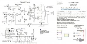
- Tubelab SPP first timer build