As stated in the above link, Tubelab Inc will cease operations at the end of 2023.
At this time the Universal Driver, the TSE-II, the SSE, and the SPP are all available. There are only TWO of the SPP boards in stock at this moment however 15 more have been ordered but I don't currently have a firm delivery date. There are at least 20 each of all the other boards.
Edit, The SPP boards will be here Thursday 7/6/23.
Last edited:
I have used my EL86 SPP a lot, although it never moved out of its plastic box with a baking tray for the top plate. I did re-jig the power supply, as @Francois G mentioned, but that was mainly because I was trying to adapt the parts I had bought already, and overcome the difference in B+s needed for the driver and output tube.I think the problem is the EL86/PL84's limitation of max screen grid voltage = 250V. If you try to make a UL PP EL86 SPP using a single 270V B+, that means the 12AT7 has to run with a low plate voltage and therefore small grid bias, which means now you have limited voltage swing from that 12AT7, and it is likely to be running with a fair amount of grid current.
I also am under the impression that 'All EL86s are equal, but some are more equal than others'. My belief is that some tubes are built and tested for a specific role, whereas other are built to comply to all published performance data. So a PL84 destined for a large scale supplier of TVs, where 200V is all that is seen by G2 and plate, is going to be a more 'standard' tube than a buyer of a top make EL86. I had an issue even with 220Vdc on the screens of my PL84s. I also saw different G2 specifications between UL84s, PL84s and EL86s for different manufacturers.
If I was to do it again, and that is the plan when I tidy up the presentation, then I will be using a 250VA toroid I have on hand with two 35Vac secondaries, then using them in series with a doubler for the output tube B+, and a quadrupler or trippler for the driver stage.
Roll on winter!

@rongon,I think 340V B+ would be fine for the 12AT7.….The problem would be how to rig the SPP PCB up for 150V on the EL86 screens. I'll have to look into that. I was also hoping to make a push-pull triode amp out of this.
Attached is the .asc for the SPP using EL86-Triode and 12AT7 with 270V B+. You'll need to put in your own 12AT7 and EL86 (or 6P43P-E) models.
I’m not sure that is what you mean, but the SPP PCB has separate connections for the screens of the output tubes, so “rigging up 150 V screen“ is easy.
I’m making slow progress with my two SPP builds of a EFB (tm) based fixed-biased amp with adjustable screen supply with the goal to document some useful operating points of 6P15P-eb tubes, and followed by one for EL86/6P43P-eb. Now I worry about grid leak resistor values. Georges BOM has the grid leak resistors specified as 470k Ohm (for cathode bias) and mau need to be adjusted in my fixed bias application. The Mullard datasheet for EL84 says max Rg1-k = .3 MOhms when used in fixed bias; 1 M in cathode bias, assuminb the “Rg1-k” is in fact the grid leak resistor. The EL86 sheet says .5 MOhm . But I have not been able to find that value for the Russian 6P43P or 6P15P tubes.
Thanks for your .asc file. One day soon I will be able to use LTSpice.
Is there a schematic somewhere for the SPP? The appropriate page on the site is blank.
http://tubelab.com/designs/tubelab-spp/schematic/
http://tubelab.com/designs/tubelab-spp/schematic/
@OldHector,I also am under the impression that 'All EL86s are equal, but some are more equal than others'. My belief is that some tubes are built and tested for a specific role, whereas other are built to comply to all published performance data. So a PL84 destined for a large scale supplier of TVs, where 200V is all that is seen by G2 and plate, is going to be a more 'standard' tube than a buyer of a top make EL86.
If I was to do it again, and that is the plan when I tidy up the presentation, then I will be using a 250VA toroid I have on hand with two 35Vac secondaries, then using them in series with a doubler for the output tube B+, and a quadrupler or trippler for the driver stage.
Roll on winter!
I wondered if the red-plating you experienced could have been caused by the specified 470k grid leak resistor values being too high for your specific tubes. According to the datasheet I checked it seems the EL86/PL84 should be OK with that. Just a thought.
@Ybolg,
https://www.diyaudio.com/community/threads/easy-diy-tube-amp.384618/page-6
See post #116 for Steve Moreley’s handy annotated version of the schematic. That is what I used.
https://www.diyaudio.com/community/threads/easy-diy-tube-amp.384618/page-6
See post #116 for Steve Moreley’s handy annotated version of the schematic. That is what I used.
Last edited:
About 12 years ago a design contest for a guitar amp that cost under $100 ran here. It has become a sticky in the Instruments and Amps forum here:
https://www.diyaudio.com/community/threads/the-hundred-buck-amp-challenge.190738/
I made two working amps for that contest. One was a minimal cost 4 watt 4 tube push pull amp that consumed about USD $45 at the time (12 years ago). The other was an amp that used every penny of the $100 budget to ROCK the loudest and squeeze into budget. Again prices are a bit higher now. I still use the 4 watt amp whenever I play through an amp. The $100, 18 watt amp hasn't seen power since 2014.
The big amp did however use UL84's and UCC85's. The schematic is attached. The power supply used an 80 VA isolation transformer that produced about 120 to 125 volts. It is rectified by a full wave bridge to run the 100 mA series string tube heaters and output tube screens on about 165 volts. The same transformer also feeds a full wave voltage doubler to power the preamp and output tube plates. I used the same supply concept for an SPP board with a separate 6.3 volt transformer to run an SPP board with 6CW5 / EL86's in it. Both the guitar amp and the SPP board made about 20 watts when powered in this manner with a "real" 3300 ohm OPT. The guitar amp only made 18 watts when I used an Antek power toroid as the OPT to fit into the $100 budget. The UL84 is a 45 volt, 100 mA version of the 6CW5 / EL86. The UCC85 is a 26 volt 100 mA version of the 6AQ8 / ECC85.
In this case you run the whole SPP board from the voltage doubled 330 volts except for the tube screens which are connected to the external 165 volt supply.
The easiest way to do a 6CW5 SPP is to use a power transformer that produces about 330 to 340 volts of B+ and use an off board "regulator" made with a mosfet or vacuum tube follower and a zener or gas tube string to create a supply in the 150 to 190 volt range. All of the 6CW5 tubes that I used were GE's pulled from discarded HP audio oscillators. I used the power transformer from the oscillator to power those amps with a zener and mosfet screen supply. GE states a 200 volt maximum for the screen voltage. All of my 6CW5 amps have used cathode bias.
"Is there a schematic somewhere for the SPP?"
My original schematic was lost when multiple computers died due to a lightning strike about 15 years ago. Fortunately forum member Ian444 had redrawn it. His schematic is included.
Attachments
Hi all,
I'm putting together the SPP board right now. As for the coupling caps, I've got some M Cap Available in my stach, but they're huge. I do have IC MWR caps (Metallized Polyester Film, the small yellow one), 630Volts, but they're only .047 mf. (it says .047K on them, so I suppose they're 0.047 mf, aren't they?). Can I use these? If not, I'll use the MCap, but they will get toasted by the tubes since they'll be pretty close to them,
Thanx for for your toughts.
Yves
Edit: The caps are close to the tubes because all the part will be on top of the board.
Last edited:
Update on the coupling caps: (see preceding post) I finally install the big cap under the board. The just enough room if I raise the board one inch. All is good.
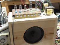
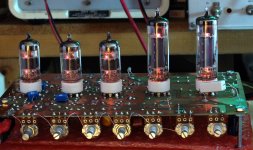
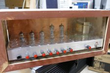
My Tubelab SPP is getting a makeover, and I am utilising some very nice Parmeko P.2642 transformers I stumbled across in an auction (part of a job lot of old transformers). They get a name check in a Wireless World article from 1956, which confirms the UL tap is 43%.

(Ignore the tubes in the picture since I have to do some excavation in my spare room to find the correct tubes and I just used any tubes on the table).

The bijou problemette is that the secondary can be wired for 4R or 16R, which will mean I need to change the feedback from the standard circuit. I shall probably use them as 4R.
The plinth is just an IKEA 12" cube cupboard which I sawed down the middle to liberate two bases. The aluminium is from a 28cm square in 3mm which is a pain to work with in my minimal kitchen tabletop workshop with a selection of drills, hole punches and files.

(Ignore the tubes in the picture since I have to do some excavation in my spare room to find the correct tubes and I just used any tubes on the table).
The bijou problemette is that the secondary can be wired for 4R or 16R, which will mean I need to change the feedback from the standard circuit. I shall probably use them as 4R.
The plinth is just an IKEA 12" cube cupboard which I sawed down the middle to liberate two bases. The aluminium is from a 28cm square in 3mm which is a pain to work with in my minimal kitchen tabletop workshop with a selection of drills, hole punches and files.
Last edited:
I have a pair of EM0776-PP transformers from Edcore which are rated at 15W, 8K primary with 25% UL taps that I had made years ago that I am going to try with a SPP board.
I also have a pair of EM0775-PP transformers from Edcore which are rated at 15W, 8K primary with 40% UL taps for comparison.
15W is way more than I need with my speakers, and the smaller transformers make the amp easier on my back.
I also have a pair of EM0775-PP transformers from Edcore which are rated at 15W, 8K primary with 40% UL taps for comparison.
15W is way more than I need with my speakers, and the smaller transformers make the amp easier on my back.
Last edited:
Does anyone see a downside to using a Nippon Chemcon LXS 400V 560uF cap as the second cap, after a 47uf and 10H choke?
This will be in an EL84 version with a 550Vct power transformer so B+ should peak below 400V.
I found I have a half dozen on hand so I might as well use one.
This will be in an EL84 version with a 550Vct power transformer so B+ should peak below 400V.
I found I have a half dozen on hand so I might as well use one.
OK, so I have the assembled board up on the bench and now am able to answer the question of which is a better UL feedback percentage for the EL84 tube, 25% or 40%.
I had two sets of transformers wound by Edcore (many years ago), EM0775-PP (40%) and EM0776-PP (25%). These are 15W PP opts 8Kp-p, with 4, 8, and 16 ohm outputs.
I am using 6P14P output tubes with a XPWR161-120 power transformer.
Vak is 288V and Ia is 33mA (conservative operation).
Max output with this power transformer and these OP transformers is about 11W.
Into a resistive load at one watt I get.
With the 40% UL transformers I get 0.12%THD.
With the 25% UL transformers I get 0.076%THD.
Ignore the absolute values, I have a measurement issue that causes measurement values typically greater than actual values.
So, this confirms that 40% UL is not set in stone, as others have concluded.
Next I plan to do some etch cuts and mod the board to support 6P1P tubes and repeat the measurements. The reason for the OPTs being only 15W is they are designed to support the 6P1P at max output, or EL84 at lower output levels than the EL84 is capable of.
I am going to do some listening tests before I do any mods.
Ultimately I may do a re-layout for 6P1P and 6N1P/6N2P combination vs USA tubes as my goal since I have an ample supply of those tubes. (12AT7 is really a better driver than either of the Soviet era tubes, but there is no Soviet era tube equivalent to the 12AT7, 12AX7 or 6DJ8 equivalents.
A redesign with 6N1P input (for gain) and 6N2P phase splitter/driver would be a better optimization but rather more complicated.
Last edited:
Miss-spoke, there is no equivalent of the 12AT7. 6N2P as input, 6N1P as driver.
The 6N2P is the equivalent of the 12AX7
the 6N1P is similar to but not equivalent of 6DJ8 Similar Mu, lower Gm
6N23P is close equivalent of 6DJ8
All three use different filament pinouts, shield between segments, not 12V with pin 9 as CT.
6N23P is getting scarce. 6DJ8 has current production, although not cheap.
6N1P and 6N2P seem to still be plentiful and relatively cheap (<$5 per tube per e-bay).
Noodling while waiting for the board:
I know both subjects are discussed here above but in context of the alternate output tube, I'll be using EL-84. I'd like to go Triode and no feedback. Looking for more detail on wiring the board for that.
Also, in looking at the Hammond 1650FA I see there's a 1608A called "improved". Any thoughts on one over the other? https://www.hammfg.com/electronics/transformers/classic/1608a-1650a
In the light of day and a lot more reading I've concluded that a 272JX and a 159R (in place of C1) with 5AR4 will give me ballpark proper voltage and that the 1650A the best choice for OPTs.
It also seems that UL is what the board is set up for and I'm in no position to attempt wiring for Triode, let alone fooling with the NFB. Besides, at 50 I had a hard enough time hearing the Triode/Pentode difference in an EL-34 P-P I built and now, 26 years later, I won't kid myself.
I'll do as I did in the SSE and wire a 100uF cap in parallel with C2. I used a pair of 47uF 630V Solens because I already had one on hand. I have 5 or 6 surplus Aerovox 30uF (the old oval ones, the good ones) but they'd need their own chassis ;-} So I'm likely to use the Solens again at $40/pair.
Hey George, I'm passing along Steve Brown's sympathy on closing down Tubelab as well as my own. It sure doesn't seem like over 20 years.
I found what I hope will be some very interesting 9 Pin PCB sockets https://www.ebay.com/itm/204366070444
They look as though they'll raise the EL-84s even further above the 12AT7 and 5AR4 which I'll put in more standard sockets.
Anyone care to comment on the transformer choices I made above? Haven't ordered them yet.
They look as though they'll raise the EL-84s even further above the 12AT7 and 5AR4 which I'll put in more standard sockets.
Anyone care to comment on the transformer choices I made above? Haven't ordered them yet.
I use those sockets, much better than ghe glazed porcelain ones.
Perhaps you can adapt the wiring for triode mode from the SSE wiring diagrams?
Perhaps you can adapt the wiring for triode mode from the SSE wiring diagrams?
A very inauspicious beginning to the BOM: Mouser and Digikey both require a 5,000 piece minimum for R2. Anyone want to buy the extra 4,999 from me?
OK, I got it down to 20 pieces of the Vishay at Digikey. I don't know why I'm laughing!
OK, I got it down to 20 pieces of the Vishay at Digikey. I don't know why I'm laughing!
Last edited:
- Home
- More Vendors...
- Tubelab
- Tubelab Simple P-P