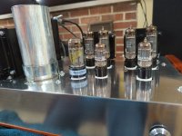
Just wanted to thank George for ordering more of these boards. Also Wall of Sound for the amazing write up and build guide. I am very happy with my finished product. This is my second tubelab build behind the sse which has been in my main system for at least 10 years.
I ended up getting a few cheaper El84 Russian military spec tubes off eBay, $30 for a quad and had the rest of the tubes from my other amp for testing. All voltages and tube dissipation seem good now. I ended up throwing in my Genelax Gold Lion tubes. I can't believe how expensive some of these tubes have become!
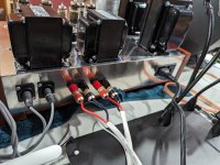
One last question as I am in the final stages of buttoning this up. I have read almost all the pages in the SPP threads I can find on here but just want to verify before my luck runs out. Im sure I am overthinking it at this point but the motor run cap is confusing me. Referring to this post:
https://www.diyaudio.com/community/threads/tubelab-simple-p-p.148694/page-36
Install one wire from the run capacitor to the black secondary lead on my power transformer and the other to ground which is my red/yellow? Or both to the black secondary leads on the power transformer?
Just a few minor things left, I need to get the right thermistor as I could find the correct one in my parts stash and tidy up some wiring.
I ended up getting a few cheaper El84 Russian military spec tubes off eBay, $30 for a quad and had the rest of the tubes from my other amp for testing. All voltages and tube dissipation seem good now. I ended up throwing in my Genelax Gold Lion tubes. I can't believe how expensive some of these tubes have become!
One last question as I am in the final stages of buttoning this up. I have read almost all the pages in the SPP threads I can find on here but just want to verify before my luck runs out. Im sure I am overthinking it at this point but the motor run cap is confusing me. Referring to this post:
https://www.diyaudio.com/community/threads/tubelab-simple-p-p.148694/page-36
Install one wire from the run capacitor to the black secondary lead on my power transformer and the other to ground which is my red/yellow? Or both to the black secondary leads on the power transformer?
Just a few minor things left, I need to get the right thermistor as I could find the correct one in my parts stash and tidy up some wiring.
Attachments
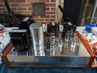

Interested in the bias adjustment mod...any link I could find that?I posted this in another thread, but wanted to share my new completed Tubelab SPP here also, in case it’s helpful to anyone undertaking a similar build. Two switchable inputs, feedback on/off switch, and two mode switches (one for each channel) to choose triode, pentode or ultra linear. Special thanks to Steve (Wall of Sound) for his great article! I also used a bias adjustment mod. Works perfectly!
View attachment 1272022View attachment 1272023View attachment 1272024View attachment 1272025
Quick question: is there a way to reduce the input sensitivity in the SPP?
I don't know what the voltage requirement for full pwr is at the moment but it seems significantly lower than my 300B amp. From the streamer there is way too much gain especially now that I am adjusting the volume with an autoformer.
I don't know what the voltage requirement for full pwr is at the moment but it seems significantly lower than my 300B amp. From the streamer there is way too much gain especially now that I am adjusting the volume with an autoformer.
Isn't a voltage divider basically a volume control which introduces noise and muddiness and leaves the imbalance in the gain unresolved? Going to autoformer was to remove the issue with resistive potentiometers altogether, and it seems it does quite nicely.
I was hoping to reduce the actual amplification factor of the first stage and scale the feedback back as needed. Maybe a 12AU or 12AY, or some other lower mu tube?
I was hoping to reduce the actual amplification factor of the first stage and scale the feedback back as needed. Maybe a 12AU or 12AY, or some other lower mu tube?
I'm surprised that the 12AT7 yields too much gain for you. Are you using global negative feedback from the output transformer secondary to the cathode of the first stage 12AT7? If yes, have you tried decreasing the value of the feedback resistor going from the output transformer secondary?
What is the value of the feedback resistor going from OPT secondary to first stage cathode?
What is the value of the cathode load resistor for the first stage 12AT7?
What is the value of the plate load resistor on the first stage 12AT7?
What are the values of the plate and cathode load resistors on the second stage 12AT7?
What is the B+ voltage to the 12AT7 stages?
I guess @grataku solved the problem? Or did he forget to look at the thread?yes, sorry for the late reply. There was nothing happening and I forgot to watch the thread
Anyway, I’m curious about the outcome of the issue for @grataku and wondered what did he do about it? I would like to try a ECC40 instead of the 12AT7 one day. The Philips datasheet gives a good example in figure 6. ECC40 has mu=32, vs 60 for 12AT7. https://frank.pocnet.net/sheets/046/e/ECC40.pdf
@rongon, To answer (most of) your questions, the schematic edited by @Steve Morley is attached below for your convenience (it must be somewhere in the thread, but I could not find it now). But it depends on grataku’s actual the implementation details. Builders usually have a B+ of 300-360 Vdc.
Last edited:
Francois thanks for re-posting the scheme to clarify. My amp is built in the prescribed way as shown, the B+is 340VDC.
Of course I did not solve the problem, I wish!🤣 🤣
My 300b amp has lower gain and fits the gain profile I am looking for better. However, the SPP has better bass. I come to believe that too much needless gain is as big an enemy to good sound as excessive feedback so I don't think that increasing the feedback as sugg by rongon is the best soln either. The ecc40 is an idea, adapting the various changes maybe above my paygrade...
I agree that getting the gain structure in your amplification stages “just right” in the first place is better than correcting later with feedback, voltage dividers, attenuators etc. However, SPP is not known for excessive gain, so I wonder what preamplification/sources you use. Would it be simpler to reduce the gain in your preamp?
I use an autoformer, passive preamp. My speakers are very sensitive and use an extremely simple, low loss x-over w/o caps so all the signal gets put into use, for lack of a better word..
To give you an idea, I have a 0.2mV MC pickup, I use the Sachin MC riaa (temporarily while I build a tube riaa) that puts out 300mV signal and with that go directly w/o additional gain into the SPP amp. And I still listen with about 1/2 volume level knob. I would really like to include the low gain version of the bartola 4P1L gyrator preamp in my chain.
To give you an idea, I have a 0.2mV MC pickup, I use the Sachin MC riaa (temporarily while I build a tube riaa) that puts out 300mV signal and with that go directly w/o additional gain into the SPP amp. And I still listen with about 1/2 volume level knob. I would really like to include the low gain version of the bartola 4P1L gyrator preamp in my chain.
I had mistakenly changed the value of R3 to 10K, This was wrong of me! I have since changed it back to the original 30K.
See attached.
The SPP has a fairly low amount of NFB.
The Leak Stereo 20 had crazy-high gain without NFB. A huge amount of NFB was used to knock the gain, and the noise, down.
Sorry for the mistake,
S.
See attached.
The SPP has a fairly low amount of NFB.
The Leak Stereo 20 had crazy-high gain without NFB. A huge amount of NFB was used to knock the gain, and the noise, down.
Sorry for the mistake,
S.
Attachments
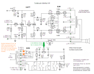
Thanks for the corrected schematic with R3 = 30k, @Steve Morley. My apologies for reposting the wrong schematic.
No sweat, Francois. It was my mistake in the first place.
For those who want a (likely slightly) lower gain SPP there is Morgan Jones's Bevois Valley EL84 amp. It's much the same as the SPP.
The Jones amp uses a regulated supply of 285 volts for the input/phase splitter tube. Some people have built it without the reg.
I won't post the circuit as it's copyrighted but here is a list of the changes needed, just refer to the SPP schematic.
Gain/phase splitter tube: 6DJ8, about half the u of a 12AT7 (change of filament wiring needed)
R100, 200 1 meg
R102, 202 330
R103, 203 0 ohms (jumper)
R104, 204 2.45K
R105, 205 330
R106, 206 47K, 2W
R107, 207 22.8K
R108, 208 22.8K
A 20.6K resistor is added between pin 3 of the 12AT7 (6DJ8 in Jones's amp) and C105
R110, 210, 114, 214 are bypassed with a 68pF capacitors
R111, 211, 115, 215 4.7K
R113, 213, 117, 217 47
C104, 106, 204, 206 470uF, 25 volts
Changes to R109 and 209 might be required to set the voltage across C102, 202 to 285 volts.
Feed back is taken from the 8 ohm secondary tap.
This sounds like a lot of change. Some like R113 etc. and C104 etc. probably don't need changing. Grid stoppers potentially not as well.
Print out the schematic and pencil in the changes. It will make more sense than just looking at my list.
Regards, S.
Feed back issue. I am using the Edcor cxpp25 -ms-8k/23% output trans and Edcor xpwr008-120 power (300-0-300) when I first hooked up feedback (330pf and 5.1k) terrible noise reversed my screens and plates one channel slight squeal other channel loud noise amp is in ultra linear and plays well without feedback
One of my SPP's (I have 3) uses the same transformers. I found that using any feedback capacitor over a few pf's caused oscillation. Do as Steve Morley suggested and use no cap."Edcor cxpp25 -ms-8k/23% output trans and Edcor xpwr008-120 power"
- Home
- More Vendors...
- Tubelab
- Tubelab Simple P-P