Hi,
Will I get away with the following xformers for a monoblock...
5VA 1x9V (For heater - will be regulated)
14VA 2x24V (For Low power to tube) (7VA per secondary)
120VA 2x25V (For LM3875TF)
These are what I can easily get hold of - and that will fit in the box...And as we all know - aestheics first, sound quality second!
Thanks,
Gaz
My PSU
Hi,
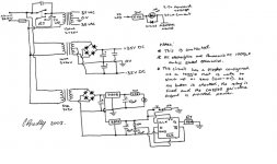
Just in case anyone is interested, I have doodled a quick schematic that will make the Hybrid Gainclone always power up with the tubes on and the Gainclone off. There is a flipflop configured as a toggle that is reset to low (zero) on power up. It will not go high until the standby button is pressed. Similarly when the button is pressed again, the gainclone section will be powered down. This does not, however, include loudspeaker relays - although doing so should be trivial.
The button I'm using has an incorperated LED so there is a circuit in there to handle that.
P.S...Please note that this is UNTESTED...
Post on here if you want the full sized version.
Just thought you may be interested...
Gaz
Hi,
Just in case anyone is interested, I have doodled a quick schematic that will make the Hybrid Gainclone always power up with the tubes on and the Gainclone off. There is a flipflop configured as a toggle that is reset to low (zero) on power up. It will not go high until the standby button is pressed. Similarly when the button is pressed again, the gainclone section will be powered down. This does not, however, include loudspeaker relays - although doing so should be trivial.
The button I'm using has an incorperated LED so there is a circuit in there to handle that.
P.S...Please note that this is UNTESTED...
Post on here if you want the full sized version.
Just thought you may be interested...
Gaz
Attachments
To be honest - I thought that there'd be more reaction to the last couple of posts. Can anyone tell me if 5VA would be suitable for the tube + a small amount of logic circuitary.
Thanks,
Gaz
Thanks,
Gaz
I am going to keep the logic so as not to damage anything. It'll always default to being switched off which seems to be the best idea. The other idea is a simple thyrister that only switches off when power is removed. However - I think that this is a more elegant solution.
BTW why would you leave out the logic? I had an email stating that the current draw for the tubes is only 4-5mA. Add to this the 71mA to drive the relay and (out of nowhere) 19mA to drive the logic, we have a total of 104-105mA where as 5VA @ 9V can provide 555mA. Well within specs.
Thanks,
Gaz
BTW why would you leave out the logic? I had an email stating that the current draw for the tubes is only 4-5mA. Add to this the 71mA to drive the relay and (out of nowhere) 19mA to drive the logic, we have a total of 104-105mA where as 5VA @ 9V can provide 555mA. Well within specs.
Thanks,
Gaz
Rarkov said:I am going to keep the logic so as not to damage anything. It'll always default to being switched off which seems to be the best idea. The other idea is a simple thyrister that only switches off when power is removed. However - I think that this is a more elegant solution.
BTW why would you leave out the logic? I had an email stating that the current draw for the tubes is only 4-5mA. Add to this the 71mA to drive the relay and (out of nowhere) 19mA to drive the logic, we have a total of 104-105mA where as 5VA @ 9V can provide 555mA. Well within specs.
Thanks,
Gaz
Hi,
1. Recalculate preresistor for LED (Ohm's law!).
2. Check 1N4148 maximum characteristics
or place this circuitry on the secondary side (I don't like LED on primary).
3. Heater current is about 0,3A.
4. Toggle switch is incorrect (input impulse former is missing).
5. Relay must be driven with a transistor and a safety diode.
6. Is the tube going to work 24/7?
regards
Hi moamps,
Thanks for your input...
1) The resistor is half the values needed for the same value in DC. By putting a diode in reverse polarity with the LED and halving the resistor value, this enables it to run from AC.
2) Make it a 1N4001 or stick it on the secondary as you mentioned. You're quite right about the 1N4148 - it only takes 100V. My mistake! Sorry! 🙁
3) Hi sorry...Wasn't paying attention. I'll try again: 300mA for heater, 71mA for relay, 19mA for logic. Comes to 400mA, which is still 155mA under spec.
4) input impulse former is missing? Sorry - can you explain? I'm not sure what you're talking about. I got it from a book and some uni notes from the 1st year! 😉
5) Yeah...I suppose so. I was hoping to get away with it but the datasheet for the flip flop chip I'm using doesn't have current handling specs in it.
6) That was the idea. Is it not advisable? I always leav my amps on. Sorry - never used tubes before...
Thanks,
Gaz
Hi,
Not only should you get the current right, easy enough to do, more importantly in a valve such as the common ECC88 / 6DJ8 you need to have the voltage within +/- 10% of 6.3V.
You can starve it a little by going, say minus to 6V without much sonic penalty, go too high and you'll see transconductance dwindle to unuseable levels within the hour.
Valves are like candles, in situations where you use a Class A, AB1 circuit like this one the valve will always conduct fully.
Unless you're sitting on a huge stash of them and I'd still resent you for this practice, it's not something I'd advise; you'r just burning candles in the wind.
Cheers,😉
3) Hi sorry...Wasn't paying attention. I'll try again: 300mA for heater,
Not only should you get the current right, easy enough to do, more importantly in a valve such as the common ECC88 / 6DJ8 you need to have the voltage within +/- 10% of 6.3V.
You can starve it a little by going, say minus to 6V without much sonic penalty, go too high and you'll see transconductance dwindle to unuseable levels within the hour.
6) That was the idea. Is it not advisable? I always leav my amps on. Sorry - never used tubes before...
Valves are like candles, in situations where you use a Class A, AB1 circuit like this one the valve will always conduct fully.
Unless you're sitting on a huge stash of them and I'd still resent you for this practice, it's not something I'd advise; you'r just burning candles in the wind.
Cheers,😉
Rarkov said:
1) The resistor is half the values needed for the same value in DC. By putting a diode in reverse polarity with the LED and halving the resistor value, this enables it to run from AC.
?
240V/10mA=24kohm
3) Hi sorry...Wasn't paying attention. I'll try again: 300mA for heater, 71mA for relay, 19mA for logic. Comes to 400mA, which is still 155mA under spec.
[/B]
Your transformer will be too close to the limit.
Use one 7806 for heating and CMOS logic, directly connect the tube (6V)
4) input impulse former is missing? Sorry - can you explain? I'm not sure what you're talking about. I got it from a book and some uni notes from the 1st year! 😉
[/B]
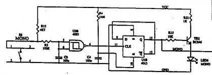
Theoreticaly, your diagram is OK. But, switches are tricky things and tend to make noise.
Look at the picture below.(CD4093 on input)
regards
Attachments
Rarkov said:2) Make it a 1N4001 or stick it on the secondary as you mentioned. You're quite right about the 1N4148 - it only takes 100V. My mistake! Sorry! 🙁
the reverse voltage on the 4148 is just the forward voltage drop on the LED or about 2v.
the 4148 will have no problem whatsoever.
OK,
Here are my new thoughts. I am lazy...I can't deny that! 😉 So my new plan is to have two relays. One will be activated after 30 seconds. The other one will be the power to the heater and plate. Hopefully (if someone can tell me how) it will be attached to a signal detection circuit and a 30 second timer.
I think I will just use a PIC to control it. Can someone point me in the direction of a simple signal detection circuit?
Maybe I should just learn to turn it off like everyone else...🙁
Thanks,
Gaz
What differences will I see if I replace the 3.3uF cap from the tube with a BG 4.7uF? Will it change things in a bad way?!
Cheers,
Gaz
Cheers,
Gaz
Rarkov said:What differences will I see if I replace the 3.3uF cap from the tube with a BG 4.7uF? Will it change things in a bad way?!
Cheers,
Gaz
Hi Gaz
As far as value goes, 3.3uF would be considered as minimum. But is this BG 4.7uF an electrolytic? As good as BG are, I still don't like an elctro of any sort in direct signal chain.
Joe R.
It is an electro - but they state that it can be used as a film cap (it's symmetrical?). It's an N type.
Thanks,
Gaz
Thanks,
Gaz
Hi,
Well there is good news and bad news...
I have music from the amp, but there is a 115mV hum. It is at 100Hz (double the UK's 50Hz?) that looks slightly like a triangle wave. My input line and speaker output pass the transformers on the way back out - but within heavy sheilding that is connected to ground (at one side). This hum is not amplified (so as I raise the music, it is drowned out).
The way my circuit is configured, the tubes are heated up first, then the gainclone is switched on. There is AC at the output when the tubes are warming, but this disappears as soon as there is a load attached. The hum starts when power is applied to the gainclone. 1000uF per rail are provided for the gainclone as close to the chip as possible.
When I try to bypass the tube (by connecting a resistor between pin 2 and 3) the hum gets worse.
Finally - will any damage be caused to the chip by leaving the plate voltage on 24/7 but disconnecting the heater only?
Thanks,
Gaz
Rarkov said:When I try to bypass the tube (by connecting a resistor between pin 2 and 3) the hum gets worse.
Hi,
You have problems with grounding scheme.IMHO
Can you post here some pictures or block diagrams?
Finally - will any damage be caused to the chip by leaving the plate voltage on 24/7 but disconnecting the heater only?
This isn't good idea.
First, generally, tube can be damaged if heater supply is off and plate voltage is on. OK, in this case plate voltage isn't so high, and tube will survival.
Second, Cathode potential will changed from -Vee to ca 0V in transition time from heating was on to steady state. In this time you must a) disconnecting speaker from GC or b) disconnecting GC from buffer.
Regards
Rarkov said:Hi,
Well there is good news and bad news...
I have music from the amp, but there is a 115mV hum. It is at 100Hz (double the UK's 50Hz?) that looks slightly like a triangle wave....
The way my circuit is configured, the tubes are heated up first, then the gainclone is switched on. There is AC at the output when the tubes are warming, but this disappears as soon as there is a load attached. The hum starts when power is applied to the gainclone. 1000uF per rail are provided for the gainclone as close to the chip as possible.
When I try to bypass the tube (by connecting a resistor between pin 2 and 3) the hum gets worse.
Finally - will any damage be caused to the chip by leaving the plate voltage on 24/7 but disconnecting the heater only?
Thanks,
Gaz
Hi Gaz
A few things to look at. The power supply to the tube buffer, can you give some details? The earlier diagram was inadequate if you followed it. This is the proper one:
An externally hosted image should be here but it was not working when we last tested it.
The hum from the tube is amplified by the gainclone chip, so it's still possible the hum comes before that. You need to establish that.
Triangular hum does seem to indicate it is mains (power supply) related.
You say "When I try to bypass the tube (by connecting a resistor between pin 2 and 3 the hum gets worse" - I assume you have disconnected power to the tube buffer before doing this? In that case it could be an indication hum is coming from gc chip circuit. It could be unstable. Have you followed the earthing instructions precisely?
The following diagram comes from this page: http://members.ozemail.com.au/~lisaras/ps.htm
An externally hosted image should be here but it was not working when we last tested it.
Hope that helps.
Joe R.
Nuuk said:I will also be in the fortunate position to compare a basic ICG with the two buffered versions!
. 🙂
Any feedback on this?
Hi,
OK, I'm getting there. With all other gainclones, I'd soldered the small signal components to a "ground bar" made up from the two cap legs soldered together. I have changed this and with a bit of playing around, I have gotten down to a 79-80mV hum. Again, this is not amplified. I can drown this hum out very easily with music. I have the modified PSU schematic already in place, and even if I add more, nothing changes.
What is the purpose of the capacitor and resistor going from the +IN to ground?
Thanks,
Gaz
- Status
- Not open for further replies.
- Home
- Amplifiers
- Chip Amps
- Tube with Power IC Output Stage - JLTi