planet10 said:
Are you talking about the thingys that Allen said were an upgrade to the bottom of the Vacuum State cascode?
dave
HUSH!

VBIGC success
Well, at last I have my VBIGC working and there is a big smile on my face 🙂
I have only had it running a few hours so please don't take my comments for anything more than initial impressions.
The sound is slightly more open than my OPA627 buffered IGC but in fairness that is using a cheap pot whereas the VBIGC has a stepped attenuator. Then again the VBICG has speaker protection (Velleman 4700).
There is a distinct difference between the two amps which I can best explain as the VBIGC sounding the more airy of the two. Somehow, the OPA627 version sounds a bit 'darker'.
Now also keep in mind that I will have to match the LPF's and put a stepped attenuator into the OPA627 to do a more objective comparison.
Of the two, I think that I prefer the VBIGC but how much that is down to the time and effort that I have put into creating it, I wouldn't like to say.
I will report back later with a hopefully more objective comparison but for now I would like to thank Joe R, Peter M, and Pedja for their help in getting me this far.
BTW, it's ironic that I discovered diyAudio forums while researching for a valve buffer earlier this year. While here I discovered the Gainclone and now, nine months later I have my valve buffer!
Good work Nuuk. I followed the link and read the your article, you mention a time delay of power to the amp because of tube filament warming. Are you taking about a delay to the B+ of the tube -- which I know is quite important, or are you talking about an additional delay to the op-amp (such as the 3875) as well?
Are you taking about a delay to the B+ of the tube -- which I know is quite important, or are you talking about an additional delay to the op-amp (such as the 3875) as well?
No, just a delay before the connection to the speakers is made.
It may be better to warm up the valves before the other circuits are powered up and that can be done with a delay circuit. But as I was using the Velleman speaker protection module, I am using that to avoid any squeal' from the speakers while the filaments warm up.
Others like Peter M use the delay circuit to switch on the valve and LM3875 after the valve heaters have warmed up sufficiently. I'm quite new to using valves but have read that it may not be too important to pre-heat the valves and in any case, I usually leave my power amps, powered up all the time.
Hi,
In this case no delay is necessary whatsoever.
Moreover, at start-up no delay is needed on high voltage tube circuits either...
Most damage is done at turn of where the heater circuits discharge much faster than the B+.
Cheers,😉
Are you taking about a delay to the B+ of the tube -- which I know is quite important,
In this case no delay is necessary whatsoever.
Moreover, at start-up no delay is needed on high voltage tube circuits either...
Most damage is done at turn of where the heater circuits discharge much faster than the B+.
Cheers,😉
Somehow, the OPA627 version sounds a bit 'darker'.
hi nuuk,
i'm not shure that you reached the potential of the opa627.....did you bias it into class a with a cascoded current source and perhaps the opa627 doesn't like to drive the lpf, perhaps a buffer in the feedback loop will do the trick or best - use a opa637bp with a buf634 in a jung multiloop with inner gain 300 and outer gain 2........?
and the better supply the better sound......🙂
Yes, I am not trying to say which buffer is best, rather point out the differences that I have noted. That's why I pointed out that these were just initial reactions.
I'm sure there is much more that can be done to both versions of these buffered IGCs and the advantage of having two great sounding amps is that one can be listened to while the other is modified.
At the moment though, I could do with a little break from more work and just sit back and enjoy the music. It seems like I have been building hi-fi non-stop for most of this year.
a little break from more work and just sit back and enjoy the music
wise words......its really what its all about...!
rock on and enjoy...

So has anybody auditioned the tube buffered 'monster' with the 6 lm3886's?
Im quite interested to hear an opinion on the sound..
Im quite interested to hear an opinion on the sound..
Re: VBIGC success
We've gotta sort that out, Nuuk.😀
I'm not going to tell you to fiddle with your OPA627 buffer/filter boards.
You can try making a small board without any input/output caps/resistors to put inside your GC monoblocks, just the OPA672 as a buffer.
For perfurated universal board (veroboard, I think you call it):
On single op-amps I put a small jumper between input and output pins (solderend under), and then it stays between the socket and the board (I always use sockets).
The ground solid-core copper wire passes under the circuit, between the socket's pins (you'll se why).
Then bypass from + to ground and - to ground with 0.1uf ceramic and 22~100uf electrolythic, as near as possible to the op-amp (that ground wire is just on the right place 😀).
I usually have difficulty in changing op-amps on the sockets because of the bypass caps, they're "glued" to the socket.😉
Use a decent pot and compare again.
Sorry to give you more things to do Nuuk.😀
You do it if you whant, but let me tell you it's worth the (not much) touble.
Maby in the end you'll have to search for a better valve.😱
Nuuk said:
The sound is slightly more open than my OPA627 buffered IGC but in fairness that is using a cheap pot whereas the VBIGC has a stepped attenuator.
We've gotta sort that out, Nuuk.😀
I'm not going to tell you to fiddle with your OPA627 buffer/filter boards.
You can try making a small board without any input/output caps/resistors to put inside your GC monoblocks, just the OPA672 as a buffer.
For perfurated universal board (veroboard, I think you call it):
On single op-amps I put a small jumper between input and output pins (solderend under), and then it stays between the socket and the board (I always use sockets).
The ground solid-core copper wire passes under the circuit, between the socket's pins (you'll se why).
Then bypass from + to ground and - to ground with 0.1uf ceramic and 22~100uf electrolythic, as near as possible to the op-amp (that ground wire is just on the right place 😀).
I usually have difficulty in changing op-amps on the sockets because of the bypass caps, they're "glued" to the socket.😉
Use a decent pot and compare again.
Sorry to give you more things to do Nuuk.😀
You do it if you whant, but let me tell you it's worth the (not much) touble.
Maby in the end you'll have to search for a better valve.😱
I have finally finished one of my monoblocks! It is working great, including intelligent switch on / off using a PIC with the comparator for signal detection.
I have a tiny amount of hum when I put my head next to the speaker, but I'm not too bothered. The first version radiated "hum" all the way to the upstairs rooms! I am impressed with the sonics - very detailed. However, I find my 180W monoblock Class B amp nicer in the bass. I think I will bi-amp using these for the trebble and the 160W OptiMOS amps for the bass. However, these are initial thoughts...Have to finish the other one first!
Next up are some silver interconnects (nice ones) - with a wooden bit to keep 'em together and maybe house an RF bobbin! 😎 😉
Gaz
LPF cap value
OK, after nearly a week and trying both 680pF and 1nF caps for the LPF, I couldn't really decide which I liked best.
Anyway, I have brought the VBIGC downstairs from my testing room and put it in the 'main' system so that I can better audition the LPF alternatives.
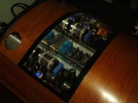
For those interested, it is now playing, fed by a modified Philips CD723 into open-baffle speakers containing rebuilt/modified Goodmans 201 drivers with piezo tweeters and it sounds $%&*$£"%^& gorgeous (that's with the 1nF cap).
The amp is on a shelf under the CD player so I don't get that view through the 'window' in the lid but there is a beautiful blue glow visible when I have the room lights low! Purrrrr.......
OK, after nearly a week and trying both 680pF and 1nF caps for the LPF, I couldn't really decide which I liked best.
Anyway, I have brought the VBIGC downstairs from my testing room and put it in the 'main' system so that I can better audition the LPF alternatives.
For those interested, it is now playing, fed by a modified Philips CD723 into open-baffle speakers containing rebuilt/modified Goodmans 201 drivers with piezo tweeters and it sounds $%&*$£"%^& gorgeous (that's with the 1nF cap).
The amp is on a shelf under the CD player so I don't get that view through the 'window' in the lid but there is a beautiful blue glow visible when I have the room lights low! Purrrrr.......
Hi
Nuuk
I am using 1000pF but having change speaker cables I may try the 680 again,I be honest the soldering iron has had a break something of a record for me.
Your amp looks great and I echo your sentiments on the sound. I know won't mind me putting it on show here.
Peter
Nuuk
I am using 1000pF but having change speaker cables I may try the 680 again,I be honest the soldering iron has had a break something of a record for me.
Your amp looks great and I echo your sentiments on the sound. I know won't mind me putting it on show here.
Peter
Attachments
GC Valve PCB wanted
Hi All
Well this thread is growing a bit I have Seen that most of you build p+ p which is a good way to go But what about all the PCB guys out there can some one help use with a Pcb and post one up using PCB express or some thing as this would be a great help to us guys
Cheers
Colin
Hi All
Well this thread is growing a bit I have Seen that most of you build p+ p which is a good way to go But what about all the PCB guys out there can some one help use with a Pcb and post one up using PCB express or some thing as this would be a great help to us guys
Cheers
Colin
Colin, you really don't need a PCB.
Do what I suggested in my email and use stripboard to mount the PSU components on. There are only three components to solder to the valve base so making up a PCB is just a waste of time.
Do what I suggested in my email and use stripboard to mount the PSU components on. There are only three components to solder to the valve base so making up a PCB is just a waste of time.
Colin
You are really on your own with PCB's.
As I said in my email you have several choices if you want an amp built around PCB's
1) BUY a JLTI I am sure Joe Rasmussen can oblige.
2) you draw your own artwork and etch the PCB's,there's even online companies that can do this.
3) perhaps if you wait long enough someone may offer PCB's.
4)Forget PCB's either use vero board or blank fibre board.
Peter
Re: GC Valve PCB wanted
Hi,
Here are the corrected schematics of my TGC, and PCBs (four) in an old Protel version.
Maybe it helps.
Regards
colin.hepburn2 said:guys out there can some one help use with a Pcb and post one up using PCB express or some thing as this would be a great help to us guys
Hi,
Here are the corrected schematics of my TGC, and PCBs (four) in an old Protel version.
Maybe it helps.
Regards
Attachments

Valve PSU
Hi again guys
Thank you All for the help hear now spoilt for choices now right my next Qs is, I have a transformer out of a old mission Cyrus I , It is a good TX but is only 21.5volts At 100VA 21.5+ 0+ 21.5 Can I getaway with that for the valve Supply It Would Save a few bucks
Thank
Colin
Hi again guys
Thank you All for the help hear now spoilt for choices now right my next Qs is, I have a transformer out of a old mission Cyrus I , It is a good TX but is only 21.5volts At 100VA 21.5+ 0+ 21.5 Can I getaway with that for the valve Supply It Would Save a few bucks
Thank
Colin
- Status
- Not open for further replies.
- Home
- Amplifiers
- Chip Amps
- Tube with Power IC Output Stage - JLTi