I recommend avoiding 6-pole choices. Use one 2-pole per channel. Much simpler connections, no crosstalk issues, lower drive current, vastly wider array of choices / mfg's.
The best reason for choosing double-throw is it allows you to choose shunt muting.(*) You want a relay that shorts the output to ground (through the series current-limiting resistor) until some time interval elapses, then the coil is energized releasing the connection to ground. That way the contacts are not required to pass signal, something that some folks dislike.😉
* without having to resort to the much harder to source 'normally-closed' contact type
Cheers
Last edited:
Rick,
Thanks for for explanation. So i would need one muting relay circuit per channel since I have the xlr outputs?
If i wanted to also mute the rca outs i could use one more muting relay circuit to do both channels? So possibly 3 muting relay circuits total?
What function does the BC547 transistor have in the circuit? post #54
Sorry but if you ask that question it is clear that you should be very careful with electronics and high voltages.
In Edelweiss-3 preamp+ I power relays from 8.6V hat I rectify for 8AL9 filament.
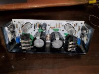
hen I sense cathode load voltage through 1 MOhm resistor and 100 uF capacitor for additional delay when tubes are hot, but caps are not charged yet. And this voltage on the 100 uF cap controls the relay through 2 MOSFETs (2 for shorter front when the relay gets powered).When powering off the preamp, filaments discharge caps in the PS pretty fast, removing voltage from the relay. You can see 2 round Soviet military relays on the board.
They shunt outputs directly to the ground.
Attachments
Wavebourn,
Thanks for the pic and explanation.
Jean-Paul,
Yes I'm a novice. This is my third audio project. Sorry if my questions seem obvious to you. I will be careful with HV.
Thanks for the pic and explanation.
Jean-Paul,
Yes I'm a novice. This is my third audio project. Sorry if my questions seem obvious to you. I will be careful with HV.
Don't be sorry, be careful. HV is not for beginners.
The BC547 is the part switching the relay. You can use many types but I would choose BC547B or C when using small telecom relays. With relays that consume more power you need another transistor.
The BC547 is the part switching the relay. You can use many types but I would choose BC547B or C when using small telecom relays. With relays that consume more power you need another transistor.
Last edited:
Jean-Paul,
If I decide to mute all outputs I would need 3 relays.
if I connect the 3 coils in parallel would one bc547 be ok to switch all 3 relays.
I see the 5v pansonic relays have a coil current of between 14-50mA
If I decide to mute all outputs I would need 3 relays.
if I connect the 3 coils in parallel would one bc547 be ok to switch all 3 relays.
I see the 5v pansonic relays have a coil current of between 14-50mA
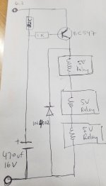
No, sorry -- that won't work. You have the coils wired in series; they will need to be wired in parallel.
Two DPDT relays are all that is needed. Eliminate C14 (post 42) and connect the RCA's feed to the XLR side of C15. The bigger capacitor won't be any help (at driving lower impedances) as long as you keep the 125k Source resistors.
BC547's are cheap; use one per relay if you keep that circuit. But I would REALLY like to talk you into finding a more inspired one. That one has at least two significant shortcomings: It doesn't reset quickly on a brief (0,5 - 3 second) power dip; even the -C gain grouping of BC547's* will just barely be guaranteed to provide 15 mA @ 5V with only 22k from 6,3V of Base drive. Maybe you could track down a logic (low threshold - saturated @5V) MOSFET-based design.
And I hate to keep carping on this, but your filament supply (post 42) is incorrect. Cold filaments demand a heavier than 2A bridge. 6,3V AC does not rectify to 6,3V DC. 1000uF capacitors are too small, and the 0,1 ohm won't do enough; the filaments will still see a lot of ripple. I would much rather see you power them straight off the secondary, and save the rectified, filtered, DC supply for a later project.
* even so, you'll need those from the higher half of the gain range -- the 'center' value is 420, which will only give 37mA at the relay's likely 'must operate' voltage of 3,75V, less still @5V
Cheers
Last edited:
The circuit in question is in use for many many years by member koifarm. From having no muting at all with a circuit putting out destructive high DC voltages to a muting circuit that has the small drawback that it does not resets quickly maybe is a bridge too far 🙂
Since there are many things to consider and reconsider I think the way of working is wrong. Normally first a design is made and people with knowledge can have a look at it and change or advise a change. In this case the thing is already built which makes it a kind of reverse way of working IMHO. Builder is (no offence) too unexperienced to work with high DC voltages or to understand simple circuits. These voltages are lethal and by no means a beginner should be near such voltages.
It seems confusion and misunderstanding will be hard to avoid. My suggestion is that the aforementioned experienced friend takes part in this thread for a safe and more efficient way of dealing with matters.
Last edited:
Rick,
Oh yes they should be wired in parallel.
Yes C14 (post 42) is supposed to help drive lower impedance loads. I have a
solid state power amp that I was gong to use until I build my tube power amp.
I looked at the caps at the 6.3v taps. They are 4700uf 25v. When measured dc voltage it's pretty close to 6.3v The 1000uf was given as a minimum, I will update the schematic. I can order a bridge rectifier that is more than 2A when i put in my order. What do you suggest. I'm also open to another option for the muting relay circuit.
Jean-Paul
My main issue is the noise coming from the amp. You've made many suggestions. Thank you for that! Some of your suggestions have nothing to do with the noise issue, and are to improve other concerns. I'm willing to try your suggestions. However in order to do so I need to order parts. So what I've been trying to do is figure out exactly what is needed for the muting relay circuit for my circumstance.
Rick PA Stadel,
Three 5V relays in series, a bipolar transistor, a protection diode, and . . .
A 16V supply should work pretty good.
Do not use a 16V supply and 5V relays in parallel.
Three 5V relays in series, a bipolar transistor, a protection diode, and . . .
A 16V supply should work pretty good.
Do not use a 16V supply and 5V relays in parallel.
Then you'll have new power sequencing issues to cause new problems.
By the way -- if you actually have 6,3VDC, from the circuit in post #42 with the filaments powered, and the transformer secondary is 6,3VAC RMS, there must be a ton of ripple.
By the way -- if you actually have 6,3VDC, from the circuit in post #42 with the filaments powered, and the transformer secondary is 6,3VAC RMS, there must be a ton of ripple.
Last edited:
Design a circuit that does not have power sequencing issues.
Or design a simple circuit that has intrinsic correct power sequencing.
"Easier said than done".
Example of a simple soft start B+ . . .
A 5Y3 with a 5V 2.0 Amp filament.
Power it with a Separate 6.3V filament winding, and connect a 0.65 Ohm resistor in series with the 5Y3 filament.
The 5Y3 Hot filament is 2.5 Ohms, but is much much less than 1 Ohm when cold.
So the 0.65 Ohm resistor takes the majority of the 6.3V during power-up.
Just use a large enough Watt rating on the 1.3 Ohm 'soft start' resistor.
We are in danger of having 100 Posts on this thread . . . and still no solution.
Think out of the box . . .
Last edited:
So I've given it some thought and I will either remove the C14 (post 42) 10ufd cap and connect the rca to pin 2 of the xlr. This way i will only need 2 relays, ither that or i will just leave the rcas un muted, since they won't get much use. Either way 2 relays will do.
So the question is will the circuit work as is, if 2 relays are put in parallel?
Rick mentioned using one BC547 per relay, but I'm not sure how that would
look. Can someone sketch it out and post?
So the question is will the circuit work as is, if 2 relays are put in parallel?
Rick mentioned using one BC547 per relay, but I'm not sure how that would
look. Can someone sketch it out and post?
Just like the earlier post, but with each transistor driving one relay. Bases connected together, Collectors connected together, and each Emitter connected to its respective relay. I'll draw it for you later this eve (presently 18:30 local) if I have time.
But never mind the connections for now(*) -- just place the order for 2 or 5 or 10, knowing that you'll have another use for them some day. And don't buy them on Ebay; you must use a reputable source -- DigiKey, Mouser, Arrow, Farnell, etc. And you must get -C suffix parts: BC547Cxx. The -A and -B devices may not have enough current gain (beta) to assure proper operation under all conditions.
* for one thing, we can try driving both relays with one transistor, take some measurements and see how hard it's struggling
Regards
Last edited:
- Home
- Amplifiers
- Tubes / Valves
- tube preamp makes rushing noise at speakers