Bigger caps also pick up signals in the environment easier but in the tube world not many care it seems. I have looked at the schematic but I pity the amplifier that will be connected to it at power on.
There should be a muting relay shorting the outputs (use series stopper resistors then) at power on especially with such high voltages possible on RCA connectors and a solid state amplifier connected. In this case output protection is not a luxury either.
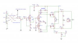
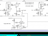
I think there is an error in the schematic as the coupling cap from the 6SL7 to 6SN7 is a short. Gate stopper resistors are too low in value with only 510 ohm. The schematic lacks stopper series resistors in all outputs. You can use 100 Ohm for that. The PSRR will be low so you wil need extremely good power supplies and extensive local decoupling (which is now lacking!). For optimal performance all stuff better would be situated close to each other on a PCB. I thinmk your device is now a transmitter. Please think of suggested changes, implement them if you like and report back. Only when all more or less standard things are done properly we can look into it when an issue still occurs.
Anyway, build what you like. IMHO you could use a way simpler circuit and have a better performing device at the same time. In 2020 one does not need much amplification with standard 2Veff sources. Most modern amplifiers already amplify enough so a buffer is adequate. Truth be told: most modern semiconductor amplifiers don't even need a buffer at all. Less = more.
There should be a muting relay shorting the outputs (use series stopper resistors then) at power on especially with such high voltages possible on RCA connectors and a solid state amplifier connected. In this case output protection is not a luxury either.
I think there is an error in the schematic as the coupling cap from the 6SL7 to 6SN7 is a short. Gate stopper resistors are too low in value with only 510 ohm. The schematic lacks stopper series resistors in all outputs. You can use 100 Ohm for that. The PSRR will be low so you wil need extremely good power supplies and extensive local decoupling (which is now lacking!). For optimal performance all stuff better would be situated close to each other on a PCB. I thinmk your device is now a transmitter. Please think of suggested changes, implement them if you like and report back. Only when all more or less standard things are done properly we can look into it when an issue still occurs.
Anyway, build what you like. IMHO you could use a way simpler circuit and have a better performing device at the same time. In 2020 one does not need much amplification with standard 2Veff sources. Most modern amplifiers already amplify enough so a buffer is adequate. Truth be told: most modern semiconductor amplifiers don't even need a buffer at all. Less = more.
Last edited:
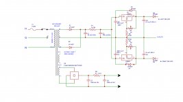
I've updated the schematic and drawing as requested. All the components should cross reference now. You can also see the power supply schematic for the 250v.
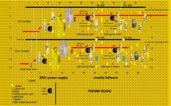
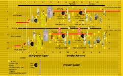
the strip board contains some of the power supply components and also some components in the preamp around the fets.
the strip board contains some of the power supply components and also some components in the preamp around the fets.
Attachments
Bigger caps also pick up signals in the environment easier but in the tube world not many care it seems. I have looked at the schematic but I pity the amplifier that will be connected to it at power on.
There should be a muting relay shorting the outputs (use series stopper resistors then) at power on especially with such high voltages possible on RCA connectors and a solid state amplifier connected. In this case output protection is not a luxury either.
I think there is an error in the schematic as the coupling cap from the 6SL7 to 6SN7 is a short. Gate stopper resistors are too low in value with only 510 ohm. The schematic lacks stopper series resistors in all outputs. You can use 100 Ohm for that. The PSRR will be low so you wil need extremely good power supplies and extensive local decoupling (which is now lacking!). For optimal performance all stuff better would be situated close to each other on a PCB. I thinmk your device is now a transmitter. Please think of suggested changes, implement them if you like and report back. Only when all more or less standard things are done properly we can look into it when an issue still occurs.
Anyway, build what you like. IMHO you could use a way simpler circuit and have a better performing device at the same time. In 2020 one does not need much amplification with standard 2Veff sources. Most modern amplifiers already amplify enough so a buffer is adequate. Truth be told: most modern semiconductor amplifiers don't even need a buffer at all. Less = more.
Hello Jean-Paul
Thank you for the informative comments.
I spoke to my friend and he commented and has some questions.
Rather than muting relays it was going to be suggested that tge preamp be used with a tube based power amp that would turn on slowly and would be turned
off first. This was to keep things as simple as possible.
I can increase the gate stopper resistor. Can you suggest what value?
As far as series stopper resistors on the output, I typically do this all the time with op-amp circuits for extra stability. Not sure of the value in a unity gain fet stage like we have here, though.
Hi a muting relay with delay is the simplest solution preventing quite a few issues. In that case the 100 ohm resistors at the outputs help to limit current when the contacts short the output. A shorted output means 0V DC and the output caps will be charged when the contacts release so no plop. Even in the case of a tube power supply you don't want any chance to have for instance 125V at either power on or power off. It is simple, very efficient, low cost and it prevents expensive repairs. It also feels like quality equipment when you use it and nothing can happen when you accidentilly switch on stuff in the wrong sequence (why would anyone take that chance at all?)..
The second goal of output resistors normally is to be able to use capacitive loads like a cable. Their third goal is that they limit current when one shorts an output while changing cables or the like. So effectively we have 3 very good reasons to include 100 Ohm output resistors as a standard in any source/pre device.
The gate stoppers could be 2.2 kOhm for a start. Use them straight at the MOSFETs gate and be sure to decouple the FETs too. A 10 Ohm resistor with 47 uF cap in each B+ line would be OK with a 0.1 uf film cap close to each FET. This also counts for the 6SN7 which has no decoupling cap/RC in the supply line.
Last but not least: make sure to use an RC filter at the inputs to prevent the preamp to be a receiver. 2.2 kOhm with a 100 pF film cap will work OK, just before the input cap C2.
* If the goal is to keep things as simple as possible you are on the wrong track. Your tube power amp does not need any effect generator to drive it. In general tube amps are high input input impedance and high amplification. An input source selection switch and volume control would then suffice without any nasty side effect.
Last edited:
The schematic does not show a gate stopper.
A true gate stopper is the only thing that connects to a gate, or it is not a gate stopper.
Good, you have protection diodes D3 and D4 on the power supply regulator ICs.
But what is the purpose of D5 and D6?
Your transformer secondary is 250V to center tap, Right?
That is 353V DC which is applied to the regulator IC Before the tubes warm up and draw current.
(no drop across the 10k, until current is drawn).
Is that IC rated for 353V input?
MOSFET followers gains are slightly less than unity.
What is the capacitance of either the XLR cable, or the RCA cable that you will use to connect to the power amplifier input?
What is the input capacitance of the power amplifier input?
What is the resistance of the power amplifier input?
That might be helpful to find what resistance you can try from the MOSFET Source to the output cap.
Last edited:
Jean-Paul
Thank you for all the info for suggestions to help get my preamp working properly. I'm not familiar with muting relays. Do you have one you could recommend? My Preamp is pretty tight so it will be tricky to figure out where
I'm going to put all these added components.
Thank you for all the info for suggestions to help get my preamp working properly. I'm not familiar with muting relays. Do you have one you could recommend? My Preamp is pretty tight so it will be tricky to figure out where
I'm going to put all these added components.
Hi a muting relay with delay is the simplest solution preventing quite a few issues. In that case the 100 ohm resistors at the outputs help to limit current when the contacts short the output. A shorted output means 0V DC and the output caps will be charged when the contacts release so no plop. Even in the case of a tube power supply you don't want any chance to have for instance 125V at either power on or power off. It is simple, very efficient, low cost and it prevents expensive repairs. It also feels like quality equipment when you use it and nothing can happen when you accidentilly switch on stuff in the wrong sequence (why would anyone take that chance at all?)..
The second goal of output resistors normally is to be able to use capacitive loads like a cable. Their third goal is that they limit current when one shorts an output while changing cables or the like. So effectively we have 3 very good reasons to include 100 Ohm output resistors as a standard in any source/pre device.
The gate stoppers could be 2.2 kOhm for a start. Use them straight at the MOSFETs gate and be sure to decouple the FETs too. A 10 Ohm resistor with 47 uF cap in each B+ line would be OK with a 0.1 uf film cap close to each FET. This also counts for the 6SN7 which has no decoupling cap/RC in the supply line.
Last but not least: make sure to use an RC filter at the inputs to prevent the preamp to be a receiver. 2.2 kOhm with a 100 pF film cap will work OK, just before the input cap C2.
* If the goal is to keep things as simple as possible you are on the wrong track. Your tube power amp does not need any effect generator to drive it. In general tube amps are high input input impedance and high amplification. An input source selection switch and volume control would then suffice without any nasty side effect.
6A3sUMMER
I forgot to update the zener and gate stopper in the schematic. I did change that on the strip board as you suggested, but only on one side as a test to see if it helped with the noise.
D5 and D6 are carry overs from Eli Duttman's power supply for his modded rca phono stage. Eli Duttmann's phono preamp voltages
post #20
I don't have an XLR Cable built yet. I did buy the cable and the xlr ends. In order to find out the capacitance, do i need to build it and measure? same for RCAs?
The power amp that i ultimately plan on using is not built yet. I'm starting to get parts for it now.
The schematic does not show a gate stopper.
A true gate stopper is the only thing that connects to a gate, or it is not a gate stopper.
Good, you have protection diodes D3 and D4 on the power supply regulator ICs.
But what is the purpose of D5 and D6?
Your transformer secondary is 250V to center tap, Right?
That is 353V DC which is applied to the regulator IC Before the tubes warm up and draw current.
(no drop across the 10k, until current is drawn).
Is that IC rated for 353V input?
MOSFET followers gains are slightly less than unity.
What is the capacitance of either the XLR cable, or the RCA cable that you will use to connect to the power amplifier input?
What is the input capacitance of the power amplifier input?
What is the resistance of the power amplifier input?
That might be helpful to find what resistance you can try from the MOSFET Source to the output cap.
output of valve preamp showing a high voltage when turned on
Post #10.
MOD: Mini Output Delay - a headphone / line-level audio output delay retrofit PCB
Ultrasmall version.
Please note that the "shorting output to GND" approach works best in your application.
Post #10.
MOD: Mini Output Delay - a headphone / line-level audio output delay retrofit PCB
Ultrasmall version.
Please note that the "shorting output to GND" approach works best in your application.
Last edited:
Thanks for the link for the muting relay. How would you mount something like that? My preamp has a bipolar power supply that is +/- 15v. I can use that to power it.
I would like to try and follow your recommendations. It won't be easy because I have to figure out how to retrofit the components on a preexisting setup.
First step I need to understand what your suggestions look like on the schematic, I can then update the schematic. Then I can order parts and start to plan on how to add them to the build.
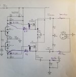
These maybe obvious questions, but remember I'm a novice. Can you clarify about the RC filter at the input. After the input switch do I connect the 2.2k resistor in series and then on the other side of the 2.2.k have a 100pf cap going to ground? Like the sketch i made?
How about the 10ohm and 47uf cap for the b+. Is it similar resistor in series and cap to ground?
The 2.2k gate stopper resistor should it be carbon composite? That's what the 510 was.
I'm also uploading a schematic where I've drawn in the output resistors and the 2.2k gate stopper resistor. Is my understanding correct?
I would like to try and follow your recommendations. It won't be easy because I have to figure out how to retrofit the components on a preexisting setup.
First step I need to understand what your suggestions look like on the schematic, I can then update the schematic. Then I can order parts and start to plan on how to add them to the build.
These maybe obvious questions, but remember I'm a novice. Can you clarify about the RC filter at the input. After the input switch do I connect the 2.2k resistor in series and then on the other side of the 2.2.k have a 100pf cap going to ground? Like the sketch i made?
How about the 10ohm and 47uf cap for the b+. Is it similar resistor in series and cap to ground?
The 2.2k gate stopper resistor should it be carbon composite? That's what the 510 was.
I'm also uploading a schematic where I've drawn in the output resistors and the 2.2k gate stopper resistor. Is my understanding correct?
Hi a muting relay with delay is the simplest solution preventing quite a few issues. In that case the 100 ohm resistors at the outputs help to limit current when the contacts short the output. A shorted output means 0V DC and the output caps will be charged when the contacts release so no plop. Even in the case of a tube power supply you don't want any chance to have for instance 125V at either power on or power off. It is simple, very efficient, low cost and it prevents expensive repairs. It also feels like quality equipment when you use it and nothing can happen when you accidentilly switch on stuff in the wrong sequence (why would anyone take that chance at all?)..
The second goal of output resistors normally is to be able to use capacitive loads like a cable. Their third goal is that they limit current when one shorts an output while changing cables or the like. So effectively we have 3 very good reasons to include 100 Ohm output resistors as a standard in any source/pre device.
The gate stoppers could be 2.2 kOhm for a start. Use them straight at the MOSFETs gate and be sure to decouple the FETs too. A 10 Ohm resistor with 47 uF cap in each B+ line would be OK with a 0.1 uf film cap close to each FET. This also counts for the 6SN7 which has no decoupling cap/RC in the supply line.
Last but not least: make sure to use an RC filter at the inputs to prevent the preamp to be a receiver. 2.2 kOhm with a 100 pF film cap will work OK, just before the input cap C2.
* If the goal is to keep things as simple as possible you are on the wrong track. Your tube power amp does not need any effect generator to drive it. In general tube amps are high input input impedance and high amplification. An input source selection switch and volume control would then suffice without any nasty side effect.
Attachments

Make sure the 2.2k gate stopper is connected right at the gate. Do not use a long wire; do not use any length of the copper strip.
That will defeat the purpose of the gate stopper.
Someone who reads the schematic might use a long wire from the 2.2k to the gate.
That will defeat the purpose of the gate stopper.
Someone who reads the schematic might use a long wire from the 2.2k to the gate.
Gregas, the drawings are both OK and all your assumptions are right regarding the input filter, RC filter for the FETs, the gate stoppers and lastly the 100 Ohm output resistors. You forgot the 0.1 uf decoupling caps direct from the drain pins of the FETs to GND. For the muting circuit you can use the filament voltage but you will need to rectify it with a Graetz bridge and use a 1000 uf 16V filter cap. I think you can use the muting circuit with a double pole double throw (DPDT) relay at the asymmetric outputs as you use those now. If you want muting on all outputs you will need a relay with more poles or more than 1 relay!
I tend to think that D7 and D8 were installed OK in the schematic.
I tend to think that D7 and D8 were installed OK in the schematic.
Last edited:
6A3sUMMER
Yes that's the plan. I actually did that with one channel for the test.
It didn't make any difference with the white noise. I will keep the 2.2k gate stopper connected right at the gate. With no long wire; and a short copper strip, when i add the 2.2k gate stopper.
Jean-Paul
15v to 35V voltage input is what's recommended for the muting relay board you sent a link to.
Where would I put the 0.1 uf caps near the fets?
Where do they connect?
How about the 10 ohm resistor and 47uf cap. Where in the schematic should they ideally go?
I would use this muting circuit with the aforementioned Graetz bridge and 1000 uf 16V cap (diode bridge connected to the filament voltage). You can use a small telecom relay as it only shorts the outputs via 100 Ohm. It does not need to be a heavy duty relay.
The 10 Ohm and 47 uF are a filter to each FETs drain from the B+ line. I understand that these will be large and expensive caps. You can use 100 Ohm and 10 uF 400v electrolytic caps if you like. The 0.1 uf caps should be very close to each FET and straight from the D pin to GND. If you first want to find out if the device can be silent just use the 0.1 uF 400V caps as they are a minimum way to decouple the FETs. Since it seems they are oscillating we want to decouple them and use the larger value gate stoppers.
The 10 Ohm and 47 uF are a filter to each FETs drain from the B+ line. I understand that these will be large and expensive caps. You can use 100 Ohm and 10 uF 400v electrolytic caps if you like. The 0.1 uf caps should be very close to each FET and straight from the D pin to GND. If you first want to find out if the device can be silent just use the 0.1 uF 400V caps as they are a minimum way to decouple the FETs. Since it seems they are oscillating we want to decouple them and use the larger value gate stoppers.
Attachments
Last edited:
I would use this muting circuit with the aforementioned Graetz bridge and 1000 uf 16V cap (diode bridge connected to the filament voltage). You can use a small telecom relay as it only shorts the outputs via 100 Ohm. It does not need to be a heavy duty relay.
The 10 Ohm and 47 uF are a filter to each FETs drain from the B+ line. I understand that these will be large and expensive caps. You can use 100 Ohm and 10 uF 400v electrolytic caps if you like. The 0.1 uf caps should be very close to each FET and straight from the D pin to GND. If you first want to find out if the device can be silent just use the 0.1 uF 400V caps as they are a minimum way to decouple the FETs. Since it seems they are oscillating we want to decouple them and use the larger value gate stoppers.
Jean-Paul,
This is my strip board layout. The right channel (on bottom) is what the modification will look like. I've added the .1uf cap from the drain of the 2 fets to ground. Since the fets share the same 250v strip (the red line), would one 10 ohm and 47uf cap be enough for one channel? Do you think it would fit on my board? I have to look into the size of a possible 47uf cap. I guess it would have to go on the board since the circuit for the 250v is there?
Should the 2.2k resistor be C.C. or metal film? or perhaps it doesn't mater?
My first step will be to try the 2.2k gate stopper resistor and the 0.1 uf cap on the drain to ground. let's see if it helps. If not I will most likely remove the fet. My friend has suggested that it will not be needed with my tube power amps.
Attachments
Omitting the FETs will very likely solve the turn-on thump/HV problem. If you were to keep the 125k Source resistors, it's just as well -- the FETs are serving no purpose with an operating current that low. (They only give lower impedance on positive-going signal excursions; any appreciable load at all will produce more distortion.)
Still have some studying to do on your post #56. But since you're considering revisions, in the meantime please consider omitting the 6SL7 1st stage. It provides no voltage gain, and the current gain serves no purpose since the load is another local valve grid. DC coupling it to the 6SN7s forces them to an uncomfortable, and completely unnecessary operating point.
The phase splitter looks like the designer combined two different designs, losing some better qualities of each in the process. I recommend dramatically lowering the Cathode resistor value and AC-coupling the signal from the volume pot wiper, biased at ground.
If you can't tolerate the additional gain, convert to a single-tube-section phase-splitter with equal Cathode and Plate resistances. Then you'd have each '+' signal at the Cathode, each '-' signal from an AC-coupling off the Plate. Then a single 6SN7 serves both channels -- a much easier design to get working properly.
There are also some issues with the filament supply, but lets hold off on those 'til the noise problem has been defeated.
Regards
Omitting the whole circuit also will solve the thump issue 🙂 Seriously: add a muting relay in all possible circuits just for peace of mind. I run into tube installations more than I like and many seem to accept power on/off issues while there is no penalty preventing those.
This especially counts for mixed topology situations and in my idea it is good design practice to make it possible to have all possible combinations without issues.
This especially counts for mixed topology situations and in my idea it is good design practice to make it possible to have all possible combinations without issues.
Omitting the FETs will very likely solve the turn-on thump/HV problem. If you were to keep the 125k Source resistors, it's just as well -- the FETs are serving no purpose with an operating current that low. (They only give lower impedance on positive-going signal excursions; any appreciable load at all will produce more distortion.)
Still have some studying to do on your post #56. But since you're considering revisions, in the meantime please consider omitting the 6SL7 1st stage. It provides no voltage gain, and the current gain serves no purpose since the load is another local valve grid. DC coupling it to the 6SN7s forces them to an uncomfortable, and completely unnecessary operating point.
The phase splitter looks like the designer combined two different designs, losing some better qualities of each in the process. I recommend dramatically lowering the Cathode resistor value and AC-coupling the signal from the volume pot wiper, biased at ground.he
If you can't tolerate the additional gain, convert to a single-tube-section phase-splitter with equal Cathode and Plate resistances. Then you'd have each '+' signal at the Cathode, each '-' signal from an AC-coupling off the Plate. Then a single 6SN7 serves both channels -- a much easier design to get working properly.
There are also some issues with the filament supply, but lets hold off on those 'til the noise problem has been defeated.
Regards
Rick.
Thanks for all your suggestions. I've made my friend aware of your concerns. Ultimately
It's his call as I'm building this with his guidance.
Gregas, the drawings are both OK and all your assumptions are right regarding the input filter, RC filter for the FETs, the gate stoppers and lastly the 100 Ohm output resistors. You forgot the 0.1 uf decoupling caps direct from the drain pins of the FETs to GND. For the muting circuit you can use the filament voltage but you will need to rectify it with a Graetz bridge and use a 1000 uf 16V filter cap. I think you can use the muting circuit with a double pole double throw (DPDT) relay at the asymmetric outputs as you use those now. If you want muting on all outputs you will need a relay with more poles or more than 1 relay!
I tend to think that D7 and D8 were installed OK in the schematic.
Jean-Paul
The heater circuit already has a bridge rectifier and 1000uf cap. See my post # 43. So I will use that if it's ok.
I have a few questions about the muting relay setup. Perhaps you can give me some guidance?
What would the best way be to mount the muting relay components? A piece of stripboard? I'm starting to compile my list of parts for my order.
Do you have a parts list for the muting relay setup? Or the following components?
The telecom relay you referenced? I tried to look it up but haven't found the right one. It would make sense to mute all the outputs. 3 per channel so 6?
The bc547 transistor seems to have a few different types can you recommend which one I should use? Same for the 1N4002 diode. Thank you!
- Home
- Amplifiers
- Tubes / Valves
- tube preamp makes rushing noise at speakers