Hey guys thanks for all the advice and things to try.
6A3sUMMER
I haven't made any changes yet. I wanted to hear what everyone has to say and then decide what to try. Moving the grid stop resistor right on the gate, will be something i will try. I have to figure out the logistics of the move in order so that the grid stopper resistor is between the zener and the gate.
Thanks for all the explanation about Capacitance Inductance and fets.
I'm still a newbie to electronics and audio so i appreciate it. my plan is to try
and eradicate the noise.
here's what the noise actually sounds like.
Voice 150 Mp3 by John Tyler | Free Listening on SoundCloud
it would be nice if moving the zener and grid resistor and trimming the copper rails will fix this.
If you remove the first tube, does the noice go away? Same with second tube? I doubt you will be able to hear the mosfet’s noise.
Regards, Gerrit
Regards, Gerrit
gerrittube,
In the schematic in Post # 1, the 6SL7 input tube is a cathode follower.
And the quiescent DC voltage output of that cathode follower turns on the 6SN7 tube (the next stage).
Pulling out the 6SL7 will turn off the 6SN7. 6SN7 tubes do not make noise when they are turned off (at least not without filament/cathode leakage / or short to the plate).
gregas,
1. If you mistakenly swapped the Zener connections, the FETs would be at or below their rated Threshold Voltage.
Under those conditions, they would be extremely noisy.
2.Do you have another 6SL7 tube to try?
1. If you mistakenly swapped the Zener connections, the FETs would be at or below their rated Threshold Voltage.
Under those conditions, they would be extremely noisy.
2.Do you have another 6SL7 tube to try?
Last edited:
6A3sUMMER
I double checked the zener orientation. They are correct.
I do have another 6sl7 to try.
My plan is to work on one chsnnel. place the 510r and zener as you suggested , replace
2 of the fets, and trim the copper traces.
I should be able to do that in the next 2 days or so.
I double checked the zener orientation. They are correct.
I do have another 6sl7 to try.
My plan is to work on one chsnnel. place the 510r and zener as you suggested , replace
2 of the fets, and trim the copper traces.
I should be able to do that in the next 2 days or so.
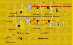
Here's what the proposed changes look like. The bottom (right channel)
The 510r is right on the gate. The resistor is between the gate and the zener.
I'm also going to replace both fets on this channel and trim the copper traces on this channel.
The 510r is right on the gate. The resistor is between the gate and the zener.
I'm also going to replace both fets on this channel and trim the copper traces on this channel.
Attachments
If you remove the first tube, does the noice go away? Same with second tube? I doubt you will be able to hear the mosfet’s noise.
Regards, Gerrit
I tried with the 6sl7 removed. The volume was diminished but i can still hear
music and the same noise.
I removed all tubes and only the noise remains.
I also tried another 6sl7. Same noise
Last edited:
If you remove the B+ to the MOSFET’s, then the noise is gone? Both with and without tubes?
Regards, Gerrit
Regards, Gerrit
gregas,
1. One idea that occurs to me, is that the MOSFET Source Followers are driving the cable capacitance of the XLR cable, plus whatever input capacitance and input resistance of the amplifier XLR input that they connect to.
What is the XLR cable capacitance, and what is the amplifier's input capacitance and resistance of its XLR input?
That might cause the MOSFETs to oscillate (at higher than audio frequencies).
Just for a trial to prove if that is a problem, put a 1k Ohm non inductive resistor in series with the Source's output capacitor.
That might do it.
2. I am having trouble looking at your vector board, and seeing it in my minds eye, as if it were a schematic.
But I think that Post #1 and Post # 26 do not agree.
Where are all those additional diodes that I do not see in Post # 1?
Your schematic only has 2 MOSFETs. But your vector board Post # 26 shows 6 MOSFETs.
A total update of your schematic might be in order (not just the 510 Ohm gate stopper and Zener connections).
Last edited:
The 2 mosfet looking items on the left are voltage regulators. The extra
Diodes and items are for the power supply . I can post the power supply
Schematic if you'd like. I will look into your other suggestions. Thank you for your
Input
Diodes and items are for the power supply . I can post the power supply
Schematic if you'd like. I will look into your other suggestions. Thank you for your
Input
If you remove the B+ to the MOSFET’s, then the noise is gone? Both with and without tubes?
Regards, Gerrit
The 250v comes across the veroboard. So its
Not so easy to remove. What will that tell you?
gregas,
1. One idea that occurs to me, is that the MOSFET Source Followers are driving the cable capacitance of the XLR cable, plus whatever input capacitance and input resistance of the amplifier XLR input that they connect to.
What is the XLR cable capacitance, and what is the amplifier's input capacitance and resistance of its XLR input?
That might cause the MOSFETs to oscillate (at higher than audio frequencies).
Just for a trial to prove if that is a problem, put a 1k Ohm non inductive resistor in series with the Source's output capacitor.
That might do it.
2. I am having trouble looking at your vector board, and seeing it in my minds eye, as if it were a schematic.
But I think that Post #1 and Post # 26 do not agree.
Where are all those additional diodes that I do not see in Post # 1?
Your schematic only has 2 MOSFETs. But your vector board Post # 26 shows 6 MOSFETs.
A total update of your schematic might be in order (not just the 510 Ohm gate stopper and Zener connections).
Right now I'm not using any xlr cable. I'm using the rca outs.
I was running into the boyuu a9 i built with help from the thread here.
Today i tried my preamp with a SS power amp. I believe the input impedance is 20k
It was extremely noisy and hatd to play music on it.
My friend checked the b+ on his scope and it didn't show signs of the noise.
I'm in the process of updating my schematics and layouts so all
Component labels jive.
The input impedance of an amplifier is almost always not properly specified.
It usually consists of a resistance, that is in parallel with a capacitance.
Most manufacturers are too lazy to list both the resistance and the capacitance,
or marketing decides not to confuse the un-knowledgeable customer with the listing of the capacitance.
XLR cables have capacitance.
RCA Phono cables have capacitance.
Have your friend put his scope on AC Coupled, then turn up the scope sensitivity (mV/divistion), and look for the noise on the B+.
Then also have your friend put the scope back to DC coupled, and look at the output of the preamp After the output coupling cap.
It would be helpful if he could measure the amplitude of the noise.
Do that with the RCA cables connected, and then do it without the RCA cables connected.
Then repeat with the XLR cable connected.
Measurements are like doing detective work, some detectives are better than others;
some measurement techniques are better than others.
You'll probably need some bypassing closer to the output MOSFETs, too. (Assuming ultrasonic oscillation is at least part of the noise problem.)
Also wondering how you chose 510R for the Gate stoppers .. That seems rather low for a Source-follower with a 125k load resistor.
Also, but probably not part of the noise issue, you have impedance *going backwards*. Instead of high-impedance inputs and low-impedance outputs, you have relatively low impedance input (some fraction of 20k) and several times that out of the Source followers.
The input stage is redundant -- as a Cathode-follower it provides no gain, only 'impedance buffering'. But the 2nd stage phase splitter would be perfectly happy driven directly by (through the same coupling cap) the volume control. (But it would need a DC return path.)
It looks like (on ...preamp_2020-11-01-jpg) a coupling capacitor might have been removed. DC coupling the 1st to 2nd stages forces the 6SN7 to conduct far more heavily than it would probably prefer (will be less linear). It'll also be very hard to balance, especially since positive signal excursions may start to conduct appreciable Grid current.
C5 (if you keep it) will need to be 100V or better, instead of 20V.
With the Volume all the way up, the design is unity gain to the RCA out (6dB to the XLR). Any chance you have combined parts of two different phase splitter designs? Usually this two-tube-section design would have a lower-value Cathode resistor than that of the Plate. Then there would be gain.
But feel free to set aside this bunch of stuff 'til you get the noise problem killed off. 6A3sUMMER has you on a good path. Good on ya'.😉
Cheers
Last edited:
The input impedance of an amplifier is almost always not properly specified.
It usually consists of a resistance, that is in parallel with a capacitance.
Most manufacturers are too lazy to list both the resistance and the capacitance,
or marketing decides not to confuse the un-knowledgeable customer with the listing of the capacitance.
XLR cables have capacitance.
RCA Phono cables have capacitance.
Have your friend put his scope on AC Coupled, then turn up the scope sensitivity (mV/divistion), and look for the noise on the B+.
Then also have your friend put the scope back to DC coupled, and look at the output of the preamp After the output coupling cap.
It would be helpful if he could measure the amplitude of the noise.
Do that with the RCA cables connected, and then do it without the RCA cables connected.
Then repeat with the XLR cable connected.
Measurements are like doing detective work, some detectives are better than others;
some measurement techniques are better than others.
For now i don't have any XLR cables. I bought some wire and ends but haven't made them up. The idea is to use the xlr with the power amps that will one day be made up.
I also purchased a scope a while back, but haven't had a chance to play with it. I can see if i can figure it out and take some measurements. I will keep you informed thanks.
You'll probably need some bypassing closer to the output MOSFETs, too. (Assuming ultrasonic oscillation is at least part of the noise problem.)
Also wondering how you chose 510R for the Gate stoppers .. That seems rather low for a Source-follower with a 125k load resistor.
Also, but probably not part of the noise issue, you have impedance *going backwards*. Instead of high-impedance inputs and low-impedance outputs, you have relatively low impedance input (some fraction of 20k) and several times that out of the Source followers.
The input stage is redundant -- as a Cathode-follower it provides no gain, only 'impedance buffering'. But the 2nd stage phase splitter would be perfectly happy driven directly by (through the same coupling cap) the volume control. (But it would need a DC return path.)
It looks like (on ...preamp_2020-11-01-jpg) a coupling capacitor might have been removed. DC coupling the 1st to 2nd stages forces the 6SN7 to conduct far more heavily than it would probably prefer (will be less linear). It'll also be very hard to balance, especially since positive signal excursions may start to conduct appreciable Grid current.
C5 (if you keep it) will need to be 100V or better, instead of 20V.
With the Volume all the way up, the design is unity gain to the RCA out (6dB to the XLR). Any chance you have combined parts of two different phase splitter designs? Usually this two-tube-section design would have a lower-value Cathode resistor than that of the Plate. Then there would be gain.
But feel free to set aside this bunch of stuff 'til you get the noise problem killed off. 6A3sUMMER has you on a good path. Good on ya'.😉
Cheers
Rick,
Thanks for the input. A lot of what you posted is way over my head. I'll try to answer what I can.
The mosfet follower section comes from Eli Duttman's Rca phonostage that i built. That was my first from scratch build. I was impressed how well it turned out and sounds. Eli Duttmann's phono preamp voltages
for Cap c5 I've used Cornell Dubilier film caps that are rated pretty high 2000v i think.
Like you said I'll try to fix the noise issue first, and then worry about the rest later.
Last edited:
So i had some time today.
I moved the grid resistor and zener as suggested. I also trimmed the veroboard
strips. It didn't seem to make any difference. The noise is still present.
I only made the changes to one channel. It was a pain to remove items
and replace them. Btw. I used 2 new mosfets and 2 new zeners. Just incase
had gone bad.
The input impedance of an amplifier is almost always not properly specified.
It usually consists of a resistance, that is in parallel with a capacitance.
Most manufacturers are too lazy to list both the resistance and the capacitance,
or marketing decides not to confuse the un-knowledgeable customer with the listing of the capacitance.
XLR cables have capacitance.
RCA Phono cables have capacitance.
Have your friend put his scope on AC Coupled, then turn up the scope sensitivity (mV/divistion), and look for the noise on the B+.
Then also have your friend put the scope back to DC coupled, and look at the output of the preamp After the output coupling cap.
It would be helpful if he could measure the amplitude of the noise.
Do that with the RCA cables connected, and then do it without the RCA cables connected.
Then repeat with the XLR cable connected.
Measurements are like doing detective work, some detectives are better than others;
some measurement techniques are better than others.
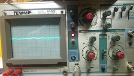
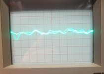
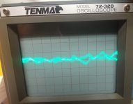
Hello 6A3sUMMER,
So I pulled out the oscilloscope I had and I'm learning how to use it for the first time.
Hopefully the measurements i took have some value.
First shot is the B+ after the 4.7k resistor in the first schematic. The time/div set at .5mS. The volts / div. set at 5 mV
2nd image set at .2 mS/div. same connection
3rd images at the RCA output. Time/ div .5mS voltage/div 5 mV set to AC coupled
4th shot same as above but dc coupled
I didn't notice much difference with the rcas attached, but i didn't try with the rcas connected from the preamp to the other amp.
Attachments

...
here's what the noise actually sounds like.
Voice 150 Mp3 by John Tyler | Free Listening on SoundCloud
...
I had same issue with a phono tube pre. The noise was generated by some 650Vdc rated mundorf oil capacitors, used at 200Vdc. I replaced them and the preamp become dead quiet.
Looking on your schematic, I'll try to replace C3 and C6.
One small hint, size matter, bigger capacitors work and sound better.
Regards,
Tibi
Last edited by a moderator:
- Home
- Amplifiers
- Tubes / Valves
- tube preamp makes rushing noise at speakers