But you did enjoy the Best of Basie, right?🙂
Here ya' go . .
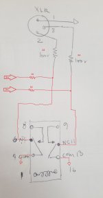
. . and no need to have both R1/R2 and R3/R4 -- but I figured you might have already mounted R3/R4 on the XLR. If so, it's fine to keep them. Just fit two more -- R1/R2. If R3/R4 aren't already placed, all you need is R1/R2. The object is two-fold: To leave some resistance when the mute relay NC contacts are otherwise connecting the outputs to ground; also helps the output stage ignore the cable capacitance.
Cheers
Here ya' go . .
. . and no need to have both R1/R2 and R3/R4 -- but I figured you might have already mounted R3/R4 on the XLR. If so, it's fine to keep them. Just fit two more -- R1/R2. If R3/R4 aren't already placed, all you need is R1/R2. The object is two-fold: To leave some resistance when the mute relay NC contacts are otherwise connecting the outputs to ground; also helps the output stage ignore the cable capacitance.
Cheers
Attachments
Rick,
Thanks for the drawing! And yes I did enjoy the Basie. It's a very nice recording. It's hard to believe it was recorded live.
I see how it's done now. nothing gets connected to 8 and 9. and the audio circuit doesn't go through the relay. What are r1 and r2 for?
Thanks for the drawing! And yes I did enjoy the Basie. It's a very nice recording. It's hard to believe it was recorded live.
I see how it's done now. nothing gets connected to 8 and 9. and the audio circuit doesn't go through the relay. What are r1 and r2 for?
It's in the last sentence of the previous post: "The object is two-fold: .."
From that era those cats could really play, huh? One take .. maybe two! Mixed live, the works. None of today's endless layering, separating into sections of related instruments, nothing but click track in the headphones, then take after take after yet another take . . .
Regards
From that era those cats could really play, huh? One take .. maybe two! Mixed live, the works. None of today's endless layering, separating into sections of related instruments, nothing but click track in the headphones, then take after take after yet another take . . .
Regards
Last edited:
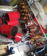
Rick my bad i got fixated on the pretty picture. R3 and R4 are not in yet.
I haven't figured out where to put them. Maybe on a terminal strip?
I haven't figured out where to put them. Maybe on a terminal strip?
IMHO you can have only R1 and R2. The relay contacts should short the outputs to GND (AFTER R1/R2) and then you still have 100 Ohm in series. No need for R3/R4: no power amplifier/device has a problem with a shorted input except when designed peculiar i.e. with quite some DC at the input. Even then a well designed device has input resistance. It was all explained that the resistors have 3 purposes in post #44. It would be OK if you pin that text and put in on the wall in your hobby room.
From no muting at all to over designing is a small step you see 😉 If you search this forum you will be very surprised to see muting (an at least 40 years old technique) with relays is a new phenomenon in many sections. Some even like the power on/off effects certainly when a big name designed the device. Then one even has to defend the muting relay technique which is tiring 🙂 Then one has to explain the slightest detail and the ever returning series/shorting to GND discussion will follow..... Then there are the naysayers who will mention non existing issues when implementing muting relays. Any Japanese mid class (or above) device in 1982 had a muting relay one way or another 🙂 So please spread this news by telex or telegraph among the tube people who are a bit behind on this subject.
Muting done with semiconductors often does have side effects. It is just muting with relays with shorting to GND that is free of that. A good source/pre is a device that has protection against power on/off phenomenons.
Last edited:
+1 jean-paul . .
Thanks for that . . especially ]the history; nothin' squashes silly like some context!
gregas, Please leave R3/R4 out.
Cheers
Thanks for that . . especially ]the history; nothin' squashes silly like some context!
gregas, Please leave R3/R4 out.
Cheers
Hey guys,
I'm having issues with the muting circuit. Perhaps some one can suggest how to troubleshoot it. Here's what it's doing. When i turn on the preamp after about 8 seconds one relay coil activates. That unmutes one xlr. The other relay doesn't activate unless i tap on it. I measured the voltage at the cap. and it slowly builds up to 2.6vdc the stays there.
Any ideas?

How many of the BC547C's do you have on hand? It's likely that one of them doesn't have high enough DC current gain to provide 40mA for the relay coil. One of the drawbacks of the circuit is that it requires fairly high gain devices, especially for a longer delay interval.
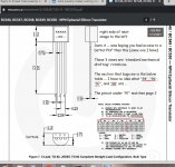
One other possibility that comes to mind -- some of the BC p/n's come in more than one pin-out. Are you sure that yours are C-B-E, left-to-right, looking at the flat face, legs down? That is one of the less-common pin-out options, by my experience at least.
Disconnect one of the Emitter-relay connections and check voltages.
Then you can lift one leg of the electrolytic to eliminate its leakage current (as a factor affecting the DC voltage, and to speed up testing).
One other point -- I recommend removing the ground connection to the relay commons. Keep the drive traces to the coil, of course. But instead of sharing the ground with the contacts, run a twisted pair or shielded lead just from the XLR to the relay contacts. Take advantage of a relay's electrical isolation whenever possible -- fewer symptom surprises to troubleshoot later -- and in the long run.
I'm not sure if some of this might've already been posted -- not going to risk a Refresh to check. Already burned the first 3 paragraphs I was trying to put here -- Cockpit Error a favorite former co-worker used to say -- with an 'inadvertent' Refresh. Sorry.
Cheers
Last edited:
Hey Rick
Thanks for the response
I ordered 10 bc547cta transistors.https://www.mouser.ca/datasheet/2/308/BC550-D-1802078.pdf The drawing confuses me I'm 100%. Can you make sense of it? Is the drawing on page 5 looking from the bottom or the top, for the view on the bottom?
Disconnect one of the Emitter-relay connections and check voltages.
where should i measure the voltage?
You also say to run a twisted pair from the xlrs to the relay contacts. Would i connect the xlr ground to the relay common?
Lower-most drawing is the bottom view.
Measure the Base voltage.
Almost. One twisted pair from Pin 1 / Pin 2, another from Pin 1 / Pin 3; each Pin 1 going to the 'armature' terminal of the relay - the one that does the 'choosing'. Remember, the object is to force 0 mV between each signal pin and ground while the capacitor charges.
The ground to the coil will have a substantial (compared to the signal noise floor) current flowing so its ground should stay separate.
Cheers
Attachments
Rick,
Thanks for the explanation. Should pin 1 (ground) from the xlrs go to pin 4 and 13 on the relay? is this the "armature"? you can see a drawing of the relay on post #121
Thanks for the explanation. Should pin 1 (ground) from the xlrs go to pin 4 and 13 on the relay? is this the "armature"? you can see a drawing of the relay on post #121
Yes. Exactly. The 'armature' is the moving part.
And keep the two grounds, Pin 4 and Pin 13, separate. Each pair of relay contacts should have its own *shorting* pair that connects only to its XLR. That avoids loops and assures that Mute will actually be Mute.
Cheers
And keep the two grounds, Pin 4 and Pin 13, separate. Each pair of relay contacts should have its own *shorting* pair that connects only to its XLR. That avoids loops and assures that Mute will actually be Mute.
Cheers
Hey Rick,
Right now the left channel input grounds are all connected together
Same for the right side grounds. They are then connected to the volume control circuit which then connects to the main chassis ground. (I have a remote controlled volume control). Thr manufacturer suggested that I do it this way.
It would be a lot easier to connect the relay ground to the chassis ground. Would that be ok? Where all the grounds connect to the chassis. The xlr ground pins already have 2 wires soldered nicely and I'm hesitant to undo it.
I haven't taken any measurements on the muting circuit yet. I should be able to do that on ghe the weekend.
But i did try to swap out the relay that wasn't firing. It seems better with the other relay relay, however they're still not firing together. Even on the same relay between one pole and the other, there's an 8 second difference.
Hey guys,
So far I've measured the voltage at the base I get 3.5 volts. The relays fire at 15 to 25 seconds. I then removed one of the transistors in measured the voltage at the base of the remaining transistor I get 4.5 volts
So far I've measured the voltage at the base I get 3.5 volts. The relays fire at 15 to 25 seconds. I then removed one of the transistors in measured the voltage at the base of the remaining transistor I get 4.5 volts
The short answer (to post #137) is, 'It would be OK, IF IT WORKS!' 😀
There's quite a bit of *art* to grounding practice, as there is *science*. (Hope I don't have to mount body armor to defend that assertion.😉)
Dunno how an DPDT relay could have an 8 second difference between poles -- there's only one armature serving both sets of contacts . . Hmm-mm . .
It is possible (and has happened), that a relay's contacts form a thin poor-conducting film after sitting on a shelf for too long. The earlier mention of having to tap on it suggests exactly that. If you have a means to drive it with a 40 to 80Hz square wave for a few 10's of seconds -- *giving it some exercise* -- should shape that up. In the bygone days of VCRs, many a head relay surrendered to that treatment. That and a touch of Cramolin, if the cover snapped off.
Regards
edit: Sorry, I was still working on this while you posted #138. Will take a minute to puzzle that -- may require a different circuit. Certainly no 5V relay should be expected to operate reliably or consistently at 3,9V (what's left at the Emitter if the Base is 4,5V).
There's quite a bit of *art* to grounding practice, as there is *science*. (Hope I don't have to mount body armor to defend that assertion.😉)
Dunno how an DPDT relay could have an 8 second difference between poles -- there's only one armature serving both sets of contacts . . Hmm-mm . .
It is possible (and has happened), that a relay's contacts form a thin poor-conducting film after sitting on a shelf for too long. The earlier mention of having to tap on it suggests exactly that. If you have a means to drive it with a 40 to 80Hz square wave for a few 10's of seconds -- *giving it some exercise* -- should shape that up. In the bygone days of VCRs, many a head relay surrendered to that treatment. That and a touch of Cramolin, if the cover snapped off.
has me wondering -- can't think of a good reason for '2 wires' . . please explain.The xlr ground pins already have 2 wires . .
Regards
edit: Sorry, I was still working on this while you posted #138. Will take a minute to puzzle that -- may require a different circuit. Certainly no 5V relay should be expected to operate reliably or consistently at 3,9V (what's left at the Emitter if the Base is 4,5V).
Last edited:
- Home
- Amplifiers
- Tubes / Valves
- tube preamp makes rushing noise at speakers