What is the filament supply voltage? It isn't really 6,3V, is it? The filaments probably won't terribly dislike 5,7V, but this circuit will!
As an Emitter Follower, this circuit provides current gain, but not voltage gain. We're expecting it to crisply turn on the relays, using the slow charge ramp of a large capacitor.
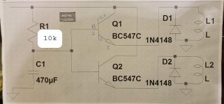
The voltages you have for one transistor operating, show ~78uA Base current, 31,2mA Emitter current, so an hFE of ~400. So you might say, 'Well then, these BC547C's must be fake' because they don't meet the -C gain group minimum hFE of 420. But that spec is given at Vce=5V and Ic=2mA! These transistors are actually doing pretty great.
The only way this circuit will work with these application constraints is if a much shorter mute interval is OK -- say, 1/2 to 1/3 what it is now. Try replacing the 22k resistor with 10k for 1/2; 6k8 for 1/3. Whether that is long enough or not is much more easily determined by testing in the circuit -- than with math exercises or simulation -- there is filament warmup time as a factor, after all. The voltmeter should be used to assess; don't plug it into a power amp just yet.
Cheers
edit: Darn it -- you beat me with the next post again!😱 Will take tonight to review your intervening post.
As an Emitter Follower, this circuit provides current gain, but not voltage gain. We're expecting it to crisply turn on the relays, using the slow charge ramp of a large capacitor.
The voltages you have for one transistor operating, show ~78uA Base current, 31,2mA Emitter current, so an hFE of ~400. So you might say, 'Well then, these BC547C's must be fake' because they don't meet the -C gain group minimum hFE of 420. But that spec is given at Vce=5V and Ic=2mA! These transistors are actually doing pretty great.
The only way this circuit will work with these application constraints is if a much shorter mute interval is OK -- say, 1/2 to 1/3 what it is now. Try replacing the 22k resistor with 10k for 1/2; 6k8 for 1/3. Whether that is long enough or not is much more easily determined by testing in the circuit -- than with math exercises or simulation -- there is filament warmup time as a factor, after all. The voltmeter should be used to assess; don't plug it into a power amp just yet.
Cheers
edit: Darn it -- you beat me with the next post again!😱 Will take tonight to review your intervening post.
Last edited:
The filament supply is 5.7ish volts.
I tried with 10k instead of 22k.
Relays fire between 6 and 8 seconds.
I'm looking for a min. of 10 seconds before the grounds are released.
I can also connect before the dropping reaistor on the filament supply and there's
About 7.4v at that location.
Basically I need a reliable circuit that offers a minimum of 10 seconds of muting on startup.
Basically we are seeing that a very basic circuit can be quite difficult 🙂
Can you draw the circuit as built? A schematic like normal, not the Veroboard style.
Can you draw the circuit as built? A schematic like normal, not the Veroboard style.
Last edited:
What is special about 10 seconds? 😉
There's another advantage to getting your capacitor-charging juice from ahead of the dropping resistor -- it'll respond quicker to dips and brown-outs -- something we haven't gone into yet, but might be worth an honorable mention, once the basics do what you want.
The supply for the Collectors of the relay drive transistors should remain connected to the 5,7V filament supply, though. Additionally, another rectifier should be added to drop another 0,6V or so. Just about any 1N400x will do.
Change R1 to 8k2, C1 to 1500uF. Change where R1 gets its juice as you mentioned -- the 7,4V before the dropping resistor. Add the rectifier in the supply to Q1 and Q2, cathode to the Collectors.
This should give a little over a 10 second delay. Note that this circuit is much better suited to shorter intervals, say 2 or 3 seconds. Don't be surprised if the relays don't activate at the same instant.
Regards
Last edited:
Ooops, almost forgot --
Still studying your grounding scheme. But those big, fabulous output coupling capacitors need to be secured mechanically (independent of their leads), connected to tie strips, then run stranded wire (or at least something more flexible than the steel component leads) from the tie point to the desired connection.
Then you can run the twisted pairs to the relays from the terminal strip -- which will easily accommodate 3 connections -- instead of trying to shoe-horn two wires into an XLR Pin 2 or 3.
Supported only by their component leads, the first long car ride with just the right frequency of vibration will cause a lead to fatigue fracture and that signal will not pass. It's especially insidious when there's secondary insulation concealing the fracture.
You have a lot of lovely work there. Very nice.
Cheers
Last edited:
Gregas, did you already try directly at the first cap as suggested when the suggestion was given to use this circuit in post #54?
*if something does not work according schematic better first determine what the differences are compared to the schematic. Here we have a tested circuit so I would look at supply voltage first.
*if something does not work according schematic better first determine what the differences are compared to the schematic. Here we have a tested circuit so I would look at supply voltage first.
Hey guys,
I've been working on this tube preamp build for a few months now, with the help of a friend. I finally finished it and noticed a rushing noise coming out of the speakers. We haven't been able to figure out how to get rid of the noise.
The noise seems to be coming from the mosfets. I double checked the vero board where the mosfets are but i don't see any mistakes. I also checked to make sure the zeners are orientated correctly and they are. The mosfets make noise with nothing connected to the gates. I.E. when the 6SN7’s have been pulled so that only the B+ is present. I've pasted the schematic hopefully you guys can see it. Does anyone have any advice?
I did a line stage that used a cathode coupled pair that had a good tube rush, I then inserted a FET ,then I applied a negative voltage to the cathodes and cleared it right up, -12 to -15VDC would be sufficient, 24 would be even better. A low noise FET would make a good ccs.
Hey guys,
JP. I just tried with the original 22k resistor and hooking up to the 7.4v at the first cap.
I get the relays firing at around between 6 to 8 seconds.
Rick. Thanks for all the suggestions. let me look at them closely and get back to you.
10 seconds is the minimum tube warm up time. I am planning to connect the output caps to a terminal strip instead of directly on the xlrs, as you suggested.
I haven't tried a larger cap yet. I have 1000uf handy. I could try that.
I just tried with a 25k resistor and the relays fire between 10 and 12 seconds.
10 to 12 secs is OK for me. I just have to live with the relays not all firing at the same
time, which is no big deal.
I just tried with a 25k resistor and the relays fire between 10 and 12 seconds.
10 to 12 secs is OK for me. I just have to live with the relays not all firing at the same
time, which is no big deal.
Try the 1000 µF cap as 10 to 12 seconds is still quite fast for a tube circuit. You could make a darlington with a power transistor and switch both relays in parallel. When in parallel they will always fire at exact the same time 😀 It should be obvious that there are practically no 2 transistors the same what explains the timing difference.
Last edited:
When your 10 extra BC547C's come in, you could sort them for a pair that behave the same (have matching DC hFE @Ic=40mA). But don't be surprised if the relays don't have exactly the same turn-on threshold, either.
If it REALLY bothers you, a 3-transistor circuit with a Zener would be only a little more complicated. It would eliminate the effect of transistor-to-transistor variations. There's plenty of space on the Vero board you have. But it would require changing some of the existing wiring.
Cheers
If it REALLY bothers you, a 3-transistor circuit with a Zener would be only a little more complicated. It would eliminate the effect of transistor-to-transistor variations. There's plenty of space on the Vero board you have. But it would require changing some of the existing wiring.
Cheers
Last edited:
I guess I have asked this before but do you have a final schematic with all your modifications?
JP
I had to look up what a Darlington is. Interesting. I would have to get some
power transistors however since I don't think I have any.
Rick I can do as you say and still power the collectors with the 5.7v and add another rectifier (1N400x) Is the 7.4v too much?
Once we sort out the muting circuit we can talk a bit more about the grounding situation.
So i put in the 1000uf cap. I get the relays going off at 16, 20 and 21secs. I can hear them clicking. There was about 3v at the base when the first relay fired.
Do you have 3 transistors and 3 relays now? You make a simpie thing complicated like that. So we solved the issue finally? 🙂
I would make it a circuit that fires all relays at the same time using just 1 transistor firing the other 3..... There are pages full of posts troubleshooting the simple muting circuit which we just solved by doing the obvious by enlarging the timing cap. Let's wrap it up. What do we learn? That ALL circuits need to be calculated, tested and then built. The way tube circuits are often thrown together empirically is not the way to go. That it then works is more luck than wisdom helped by the forgiving character of tubes (unique in electronics, just look at the details of the muting circuit). One is occupied doing something but it is a pastime, not building a HiFi device with a specified purpose and parts that are doing their work in their most linear region. Every electronic part has a purpose and a set of parameters with which they work optimally. A good design takes those parameters into account for maximum performance so minimal distortion, noise etc.
First determine what the purpose of the circuit is and what it should do. Take into account what the environment is (impedances, required gain), design, adhere to standards, calculate, choose parts, test and then build a final product and test again.
Last edited:
- Home
- Amplifiers
- Tubes / Valves
- tube preamp makes rushing noise at speakers