More notes on triode line out summing amp
Hi
Not wanting to get into a catfight
A. I never use a computer, I just build or re-store gear. The RCA tube manual disagrees, and I often find plate values for pentodes up to 470K. Any preamp I have built, or worked on including old Neumann and other German and English classic one or two pentode designs, are super quiet compared to triodes.
I had a project about four years ago, (you have to add the two years lost due to no Moo now) where I buit a pile of preamps, 60Db flat gain, two triodes, one pentode, two pentodes, Forsell 993 discrete, transistor, FET and then we compared, and while the two triodes, and two triodes with a low Z buffer out sounded great, the pentodes ran away from all with zit for noise.
Also, most of us do not make very complex tube preamp circuits, I can post a typical two pentode circuit, that has multiple feedback, and like 80 Db gain
What I know from building and using older tube gear, have not worked with Mu and newer designs.
How much pad dampening effect can depend on the stage after, and loading etc. and the studios I have built for, like to use hot condenser mics and toss acres of level into the in trans. if your Mu stage has the swing, then you will get that hot sound of the tube at high levels, but neg feedback is also for lowest noise.
I have always noticed a diff when using pad, ask others on DIY
Some notes and a couple drawings
I have a hard time posting as way too much to do, but I dragged up some notes on tests I did, a lot of tests, on various triodes as the basic 15K primary/600 ohm Altec "Red" 15905, classic style line out trans for tube stage.
I tested, 12au7, (single triode) 6sn7, #37, #76, 6fq7/6cg7, and 6gu7
I also tested two triodes in parallel, mu stage etc..
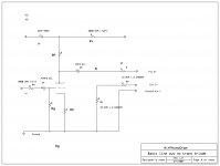
Using this drawing "Basic Line out 15K/600 ohm triode
The plate resistor seemd to like being 15k no matter what, and that had a lot to do with matching transformer impedance. If you are direct coupling the plate, then pin2+, RF, couples to CB, and the carbon resistors help to smooth out the sonics, and add some neg feedback/stability
Rg = 300 k, as overall good value for most power triodes
The surprise tube was 6gu7 as it had about 15% more out clean than any other tube.
There are a small pile of unused tubes, 6Fm7, 6ew7, 6ea8 etc, that have a low and high power triode. The 6fm7 has a ten-watt triode with a very low 760 ohm plate impedance and will drive acres of power into super low loads, but the filament power is high, and in mixers can add up.
Figures for two 6sn7 triodes in parallel, are; if RP = 16k, and RK = 560 ohm, then max out = 55 volts peak to peak, or about 40Vrms, at X, in to the transformer, which drops down to about 15V across 600 ohms due to the 12DB loss in the line out transformer
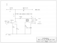
Using 12au7, 6fq7/6cg7, and 6gu7 as direct out, pin2+, RF, couples to CB, increase
RF and RG to 220 ohms to buffer load from the plate, and RG goes to ground. Then pin 3 goes to ground through a resistor, so if you are driving a transformer, then the two resistors help the triod achive more clean level out.
RP = 5.6 to 7.5k, Rk = 200 to 330 ohm, B= up to about 175 volts, or up to 75% of plate max dissipation, max idle current. CB = 4mfd or up to a ten mfd, metal poly CDE or solens cap, but size can be a problem
For a single triode low z out, 5963/12au7, Rk = 330 ohm, Rp = 7.5k, 4mfd and two 330 ohm buffers, 150V B+
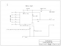
For a 5751 or 12ax7, summing amp, 100k summing resistors, 1meg neg feedback from plate to grid, 1K cathode resistor, 82k to 100k plate, 150 volts B+
Look at the Summing_amp_triode pic
I was building gear that ran off a 12Volt AC wall wart, to a 12V ac transformer backwards for B+ inside the rack case, and that gave me about 150 volts+, and 12Vdc
for fills
I have to make up some more drawings, and how to make a grid...
Look at the drawing, Line_out_triode_no_trans
Again, one 6gu7, with both triode in parallel, will give you the most power out, and very warm, smooth tone, not too much fill power
I also tried and used, when building a Mu stage, two triodes on the bottom, and one on top. Two 12au7 triodes on bottom, and one on top gave a lot more power and lower Z out than one on top/bottom.
Anyway, I have noodled around building a tube mixer, and worked on quite a few, interesting stuff. I have a few times, a long time ago, ran into a pile of tube mixers that came out of film and other sound studios. Most used 12au7 throughout, and 5879 pentodes for 1st stage
I will try and post more next week...
Hi
Not wanting to get into a catfight
A. I never use a computer, I just build or re-store gear. The RCA tube manual disagrees, and I often find plate values for pentodes up to 470K. Any preamp I have built, or worked on including old Neumann and other German and English classic one or two pentode designs, are super quiet compared to triodes.
I had a project about four years ago, (you have to add the two years lost due to no Moo now) where I buit a pile of preamps, 60Db flat gain, two triodes, one pentode, two pentodes, Forsell 993 discrete, transistor, FET and then we compared, and while the two triodes, and two triodes with a low Z buffer out sounded great, the pentodes ran away from all with zit for noise.
Also, most of us do not make very complex tube preamp circuits, I can post a typical two pentode circuit, that has multiple feedback, and like 80 Db gain
What I know from building and using older tube gear, have not worked with Mu and newer designs.
How much pad dampening effect can depend on the stage after, and loading etc. and the studios I have built for, like to use hot condenser mics and toss acres of level into the in trans. if your Mu stage has the swing, then you will get that hot sound of the tube at high levels, but neg feedback is also for lowest noise.
I have always noticed a diff when using pad, ask others on DIY
Some notes and a couple drawings
I have a hard time posting as way too much to do, but I dragged up some notes on tests I did, a lot of tests, on various triodes as the basic 15K primary/600 ohm Altec "Red" 15905, classic style line out trans for tube stage.
I tested, 12au7, (single triode) 6sn7, #37, #76, 6fq7/6cg7, and 6gu7
I also tested two triodes in parallel, mu stage etc..
Using this drawing "Basic Line out 15K/600 ohm triode
The plate resistor seemd to like being 15k no matter what, and that had a lot to do with matching transformer impedance. If you are direct coupling the plate, then pin2+, RF, couples to CB, and the carbon resistors help to smooth out the sonics, and add some neg feedback/stability
Rg = 300 k, as overall good value for most power triodes
The surprise tube was 6gu7 as it had about 15% more out clean than any other tube.
There are a small pile of unused tubes, 6Fm7, 6ew7, 6ea8 etc, that have a low and high power triode. The 6fm7 has a ten-watt triode with a very low 760 ohm plate impedance and will drive acres of power into super low loads, but the filament power is high, and in mixers can add up.
Figures for two 6sn7 triodes in parallel, are; if RP = 16k, and RK = 560 ohm, then max out = 55 volts peak to peak, or about 40Vrms, at X, in to the transformer, which drops down to about 15V across 600 ohms due to the 12DB loss in the line out transformer
Using 12au7, 6fq7/6cg7, and 6gu7 as direct out, pin2+, RF, couples to CB, increase
RF and RG to 220 ohms to buffer load from the plate, and RG goes to ground. Then pin 3 goes to ground through a resistor, so if you are driving a transformer, then the two resistors help the triod achive more clean level out.
RP = 5.6 to 7.5k, Rk = 200 to 330 ohm, B= up to about 175 volts, or up to 75% of plate max dissipation, max idle current. CB = 4mfd or up to a ten mfd, metal poly CDE or solens cap, but size can be a problem
For a single triode low z out, 5963/12au7, Rk = 330 ohm, Rp = 7.5k, 4mfd and two 330 ohm buffers, 150V B+
For a 5751 or 12ax7, summing amp, 100k summing resistors, 1meg neg feedback from plate to grid, 1K cathode resistor, 82k to 100k plate, 150 volts B+
Look at the Summing_amp_triode pic
I was building gear that ran off a 12Volt AC wall wart, to a 12V ac transformer backwards for B+ inside the rack case, and that gave me about 150 volts+, and 12Vdc
for fills
I have to make up some more drawings, and how to make a grid...
Look at the drawing, Line_out_triode_no_trans
Again, one 6gu7, with both triode in parallel, will give you the most power out, and very warm, smooth tone, not too much fill power
I also tried and used, when building a Mu stage, two triodes on the bottom, and one on top. Two 12au7 triodes on bottom, and one on top gave a lot more power and lower Z out than one on top/bottom.
Anyway, I have noodled around building a tube mixer, and worked on quite a few, interesting stuff. I have a few times, a long time ago, ran into a pile of tube mixers that came out of film and other sound studios. Most used 12au7 throughout, and 5879 pentodes for 1st stage
I will try and post more next week...
Attachments
Not wanting to get into a catfight
Agreed!
A. The RCA tube manual disagrees, and I often find plate values for pentodes up to 470K.
I am sure you have seen 470K plate values. But as soon as you add the load and NFB network the effective plate load and hence the real gain is much lower. Also, a 470K load means a very low plate current which means a lower gm which means lower gain and higher noise - not a winning combination for a preamp.
Any preamp I have built, or worked on including old Neumann and other German and English classic one or two pentode designs, are super quiet compared to triodes.
Clearly you have experienced some dreadful triode designs. Check out the Radiotron Designers Handbook page 783 for the differences between the noise generated by triodes and pentodes and their recommendation for the first stage of a preamp. Note that many early design used pentodes wired as triodes.
but neg feedback is also for lowest noise.
This is a common misunderstanding - NFB does not improve signal to noise ratio.
I am puzzled by your summing amplifier based on a single 12AU7. This has insufficient open loop gain to produce anything resembling the virtual earth of a true NFB summer and its performance will be little different to that of passive summing network.
Cheers
Ian
More pentode duke outs
Hi
I think the summing amp ended up with a 12ax7 or a 5751.
I make several drawings before building, then build, test, then a final drawing or mark over the current one. One drawing is marked 5963, I got a pile of those, quality 12au7 tubes, and a later drawing is marked 5751.
As far as gain and all that, again, I just build and test with Mr. Scope, and Mr. oscillator. The in resistors in this circuit go to the center taps on the filter pots, so the resistance to ground is varied with the pot.
I detected no or almost zero interaction between inputs.
Increasing the negative feedback to zero out the junction where the feedback meets the input, will zero interaction.
One of these five band EQs is in a studio in Escondido, and has been used almost weekly for about five years, and the last time I saw it, I could not hear any interaction between the bands.
I remember being happy with this circuit as the EQ in/out had no level change or clicks/pops, and the bands worked independent of each other.
I always find tube circuits usually have a mind of their own, and maybe that software does not have enough data from the past installed??
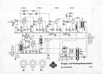
Here is a schematic of the preamp for a EMT plate reverb
It uses two EF86 pentodes in series, as the pre stage, and some dual triode, maybe similar to a 12au7 as line driver.
There is also, at the bottom, a single pentode gain stage.
The two at the top, are surronded by positive and negative feedback from the second tube to the first. Older circuits like these used Neg feedback to control the bad effects tubes had, and also noise.
So, I am saying that while I have seen talk about partion noise on the forums, having worked with complex pentode circuits like these, I know that they had acres of gain, usual around 80DB, and super quiet.
I re-built some Gates preamps about six years ago. They had two EF98 tubes, and I was astonished that they were almost 70DB of gain. That was back when there were no pads, and were controlled with volume/level controls.
And yes, pentodes, with super high plate impedances, very low current flow, that almost always drove a second tube, that gave a high Z load, and then a low Z out.
The phono preamps that I built with 6an8 tubes, where the pentode drove the triode as the buffer and second gain stage, were much quieter than the basic two 12ax7 triodes.
I'll have to dig-up more info. I'm just packed with gear to re-pair or mod, now.
I have always looked at old circuits to see how they worked.
Here is a old Stromberg "PA" amp. They made lots of PA and other amps. This one has three 6sj7 pentodes as pre stages, mixed to a buffer, then EQ, then, the power amp.
The gain on these amps, (if you re-store them) is pretty high, more than the usual triodes, and with very low noise. Most PA amps used 6j7, then 6sj7 tubes, before the
5879 came out.
The preamps that I have built with 1940's 39/44 pentodes, with a triode second stage/buffer, at about 12DB gain, can give more than 60DB gain total, and very quiet.
I have found that with the volume levels now, that about 35Db is enough
I need to find another schematic drawing program, as the ExpressPCB one I have is lousy for tube circuits.
Then I can convert the drawings I have of the tube gear I have built and post
And, yes, I work on guitar amps, so I have seen triode/tube design from ^%$# to sweet and super fine, and those odd circuits with clever designs, can make triodes shine as well.
I like it when I have some Hi-Fi gear, to ward off the evil guitar amp stuff, amps you hate to listen to...
I always liked Fisher designs
Back a while ago, I was looking at Audiophile phono preamp designs, and one of the best was four different triodes, each providing just the amount of gain etc. to make up a super quiet 60DB for the RIAA curve
Hi
I think the summing amp ended up with a 12ax7 or a 5751.
I make several drawings before building, then build, test, then a final drawing or mark over the current one. One drawing is marked 5963, I got a pile of those, quality 12au7 tubes, and a later drawing is marked 5751.
As far as gain and all that, again, I just build and test with Mr. Scope, and Mr. oscillator. The in resistors in this circuit go to the center taps on the filter pots, so the resistance to ground is varied with the pot.
I detected no or almost zero interaction between inputs.
Increasing the negative feedback to zero out the junction where the feedback meets the input, will zero interaction.
One of these five band EQs is in a studio in Escondido, and has been used almost weekly for about five years, and the last time I saw it, I could not hear any interaction between the bands.
I remember being happy with this circuit as the EQ in/out had no level change or clicks/pops, and the bands worked independent of each other.
I always find tube circuits usually have a mind of their own, and maybe that software does not have enough data from the past installed??
Here is a schematic of the preamp for a EMT plate reverb
It uses two EF86 pentodes in series, as the pre stage, and some dual triode, maybe similar to a 12au7 as line driver.
There is also, at the bottom, a single pentode gain stage.
The two at the top, are surronded by positive and negative feedback from the second tube to the first. Older circuits like these used Neg feedback to control the bad effects tubes had, and also noise.
So, I am saying that while I have seen talk about partion noise on the forums, having worked with complex pentode circuits like these, I know that they had acres of gain, usual around 80DB, and super quiet.
I re-built some Gates preamps about six years ago. They had two EF98 tubes, and I was astonished that they were almost 70DB of gain. That was back when there were no pads, and were controlled with volume/level controls.
And yes, pentodes, with super high plate impedances, very low current flow, that almost always drove a second tube, that gave a high Z load, and then a low Z out.
The phono preamps that I built with 6an8 tubes, where the pentode drove the triode as the buffer and second gain stage, were much quieter than the basic two 12ax7 triodes.
I'll have to dig-up more info. I'm just packed with gear to re-pair or mod, now.
I have always looked at old circuits to see how they worked.
Here is a old Stromberg "PA" amp. They made lots of PA and other amps. This one has three 6sj7 pentodes as pre stages, mixed to a buffer, then EQ, then, the power amp.
The gain on these amps, (if you re-store them) is pretty high, more than the usual triodes, and with very low noise. Most PA amps used 6j7, then 6sj7 tubes, before the
5879 came out.
The preamps that I have built with 1940's 39/44 pentodes, with a triode second stage/buffer, at about 12DB gain, can give more than 60DB gain total, and very quiet.
I have found that with the volume levels now, that about 35Db is enough
I need to find another schematic drawing program, as the ExpressPCB one I have is lousy for tube circuits.
Then I can convert the drawings I have of the tube gear I have built and post
And, yes, I work on guitar amps, so I have seen triode/tube design from ^%$# to sweet and super fine, and those odd circuits with clever designs, can make triodes shine as well.
I like it when I have some Hi-Fi gear, to ward off the evil guitar amp stuff, amps you hate to listen to...
I always liked Fisher designs
Back a while ago, I was looking at Audiophile phono preamp designs, and one of the best was four different triodes, each providing just the amount of gain etc. to make up a super quiet 60DB for the RIAA curve
Attachments
Hi
I think the summing amp ended up with a 12ax7 or a 5751.
As far as gain and all that, again, I just build and test with Mr. Scope, and Mr. oscillator. The in resistors in this circuit go to the center taps on the filter pots, so the resistance to ground is varied with the pot.
I detected no or almost zero interaction between inputs.
A 12AX7 would have a much better chance of creating a true summer due to its higher mu. I am not surprised you detected no interaction between the controls. Even with passive mixing there is very little interaction.
The trouble with trying to make a true NFB summer with tubes is getting enough open loop gain. With only ten inputs, as in Antonio's mixer, and aiming only for unity gain overall, you need 20dB open loop gain just to make the virtual earth the same as it would be with a passive mixer. To get it 10 times better ( a modest target) you need another 20dB or 40dB in total. There are several ways you might achieve this,
1. Pentode - and EF86 can do this without too much trouble but it has a hard job driving a load plus the NFB network. Adding a direct coupled cathode follower to drive the load and NFB network works quite well.
2. 12AX7 mu follower. A single 12AX7 will get you about 36dB open loop gain taking account of NFB network load but will not drive any real load. A 12AX7 mu follower gets you nearly the full 100 mu (40dB) open loop and a nice low output impedance too. This seems to work well with up to 10 inputs.
3. 12AX7 cascode. This can produce 45dB or more open loop gain. It does suffer from poor distortion but the NFB helps that a lot.
Increasing the negative feedback to zero out the junction where the feedback meets the input, will zero interaction.
It will, but it brings another set of problems. The real difficulty with tube based virtual earth summers are due to the NFB stability problems at very low frequencies. Most tube amplifiers have small amounts of NFB and are not too hard to make stable. Virtual earth mixers, on the other hand, must have lots of NFB else they will not make a virtual earth. Unfortunately it is large amounts of NFB that cause stability problems, especially at low frequencies.
The 12AX7 cascode mentioned above is unconditionally stable and has 45dB of NFB. Even so, it produces a 7dB very low frequency bump with 10 sources which only gets worse with fewer sources. Now these effects take place at frequencies of a few of Hertz and below but they are enough to affect the sound.
And so far we have only been talking about 10 inputs and a modest virtual earth (nowhere near what you can achieve with an op amp). For more inputs and a better virtual earth you need more open loop gain; probably 60dB or more and and 60dB of feedback for unity gain. This is extremely difficult to do with tubes. What you really need is some tube combination that has 60dB open loop gain down to dc coupled with an NFB network that also works down to dc. When I come up with it I'll let you know!
Here is a schematic of the preamp for a EMT plate reverb
It uses two EF86 pentodes in series, as the pre stage, and some dual triode, maybe similar to a 12au7 as line driver.
There is also, at the bottom, a single pentode gain stage.
The two at the top, are surronded by positive and negative feedback from the second tube to the first.
Fixed gain twin pentode pres with NFB were common many years ago (V72 for example). I see NFB in the circuit you posted but no positive feedback. Could you please point that out for me?
Older circuits like these used Neg feedback to control the bad effects tubes had, and also noise.
As I mentioned before, NFB does not improve signal to noise ratio.
So, I am saying that while I have seen talk about partion noise on the forums, having worked with complex pentode circuits like these, I know that they had acres of gain, usual around 80DB, and super quiet.
The twin pentode designs do not have a reputation for being super quiet. Their noise performance is determined primarily by the large turns ratio transformers they used at the input, often with 30dB of gain. They had to use such a high turns ratio because of the poor noise performance of pentodes. All the later professional mixer designs like RCA and Universal Audio used triodes for their lower noise.
Cheers
Ian
mixer (Antonio e Francesco)
Ian,
we are still alive 🙂
During the last months we have had several problems ... so we neglected the realization of the mixer.
Now we have resumed the project ... and have realized a further PCB for the pots and switches of the top panel.
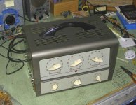
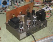
Specifically, there are two PCBs for each channel: 1 for the amplifier stages and one for the commands, both connected by means of short (7 cm) parallel wires (see photo). We tested the prototype and it seems to work properly (frequengy range 2-100 KHz, - 3 dB). We performed also several auditory tests ... and it simply seems to be not present between the source and the final amplifier...
We have also decided to order professional PCBs (dual layer). For this reason, we are evaluating the possibility of extending the project in a news group.
Now, we'd like to know (and to ask) if you are still available to help us in the final phase of the project.
Ciao
Antonio e Francesco
Ian,
we are still alive 🙂
During the last months we have had several problems ... so we neglected the realization of the mixer.
Now we have resumed the project ... and have realized a further PCB for the pots and switches of the top panel.
Specifically, there are two PCBs for each channel: 1 for the amplifier stages and one for the commands, both connected by means of short (7 cm) parallel wires (see photo). We tested the prototype and it seems to work properly (frequengy range 2-100 KHz, - 3 dB). We performed also several auditory tests ... and it simply seems to be not present between the source and the final amplifier...
We have also decided to order professional PCBs (dual layer). For this reason, we are evaluating the possibility of extending the project in a news group.
Now, we'd like to know (and to ask) if you are still available to help us in the final phase of the project.
Ciao
Antonio e Francesco
Attachments
Last edited:
Hi guys, good to hear from you again. The front panel PCB looks like a very good idea.
If you need me I am here to help.
Cheers
Ian
If you need me I am here to help.
Cheers
Ian
Results of tests
Ian,
After the addition of a 220 uF capacitor on the cathode of the bottom triode of V3, the gain has become appropriate (see the results obtained in the included file). 10, 20, 40 input mV should be to intended as 1, 2, 4 input mv (since there will be a 1:10 input trans between source and the grid of V1).
Essentially, only 3 problems remain:
- A) high level of noise on the output (but not in the intermediate stages);
- B) loss of a very excellent performance due to the output resistors;
- C) The bass control is asymmetric below 200 Hz.
A) NOISE ANALYSIS (see included file)
There is an enigmatic noise increase after R50 (the 100K resistor between bus selector S3 and vocal and bass bus). We tried to increase the input impedance of the meter (from 10Mohm to 10Gohm) or to connect to ground the vocal bus… without any reduction of the noise.
Questions:
1) Why the noise is low until V4 stage and it rapidly increases (to 15 mv) just after the 100k resistor (R50) ?
2) Why the noise is not stable with gain pot on max position?
B) FREQUENCY RANGE (see included file)
The frequency range deteriorates very much after R49 and R50 (the 100K resistors between bus selector S3 and vocal and bass bus) and after R47 and R48 (the 150K resistors between bus selector S3 and instrument bus).
Questions:
1) Why the worsening after R49 and R50 and after R47 and R48 ?
2) Is it possible to avoid the worsening of the excellent performance of the preamplifier ? Do you have a solution for that ?
C) ASYMMETRIC TONE CONTROL BELOW 200 Hz (see included file)
We already discussed (post 147) about this problem and you ascribed it to the relatively low load (around 5K) of V2 (http://www.diyaudio.com/forums/pa-systems/178476-tube-mixer-15.html#post2631232) … and you suggested to recalculate the tone control circuit for much higher values of the potentiometers (500k vs the actual 50K for VR2 and VR4). However, in another reply (post 155), you specified that the 5K load is essentially due to R16 and R15 (which totals just over 5K ohms at mid frequencies …where the two capacitors can be considered short circuits). We do not understand how also increasing VR2 and VR4 to 100-500K ... it can increase the total load of V2.
Questions:
1) How to improve the performance of the tone control below 200 Hz ?
2) Moving the added 220 uF Capacitor on the cathode of bottom triode of V3 to the cathode of bottom triode of V2 … can solve the problem ?
Ciao
Antonio e Francesco
P.S. Have you ended your mixer?
Attachments
Last edited:
Since you are using passive mixing, if you are only testing a single channel, then you need to simulate the bus resistors of all the other not present channels. So if you plan to have 10 channels, then when testing only one, you need to add 100K/9 ~ 11K resistor across R52, for example, to simulate the unconnected channels on the vocal bus. The same applies for the other buses.A) NOISE ANALYSIS (see included file)
There is an enigmatic noise increase after R50 (the 100K resistor between bus selector S3 and vocal and bass bus). We tried to increase the input impedance of the meter (from 10Mohm to 10Gohm) or to connect to ground the vocal bus… without any reduction of the noise.
Questions:
1) Why the noise is low until V4 stage and it rapidly increases (to 15 mv) just after the 100k resistor (R50) ?
2) Why the noise is not stable with gain pot on max position?
This is almost certainly the same problem and is caused by cable capacitance across the 1Meg resistor at the input to V6 for example. If you include the 11K to ground to simulate the other channels connected to the bus the frequency response should be restored.B) FREQUENCY RANGE (see included file)
The frequency range deteriorates very much after R49 and R50 (the 100K resistors between bus selector S3 and vocal and bass bus) and after R47 and R48 (the 150K resistors between bus selector S3 and instrument bus).
Questions:
1) Why the worsening after R49 and R50 and after R47 and R48 ?
2) Is it possible to avoid the worsening of the excellent performance of the preamplifier ? Do you have a solution for that ?
You need to scale ALL of the components of the tone control circuits. So for example all the resistors and pots should be increased by say 10 times and all the capacitors decreased by 10 times. A factor of 10 may not be necessary. For example, if you used a factor of 4.4 then this would make VR2 = 220K, R16 = 22K, R15 and R17 = 2.2K, C6 = 22nF and C5 = 220nF.C) ASYMMETRIC TONE CONTROL BELOW 200 Hz (see included file)
We already discussed (post 147) about this problem and you ascribed it to the relatively low load (around 5K) of V2 (http://www.diyaudio.com/forums/pa-systems/178476-tube-mixer-15.html#post2631232) … and you suggested to recalculate the tone control circuit for much higher values of the potentiometers (500k vs the actual 50K for VR2 and VR4). However, in another reply (post 155), you specified that the 5K load is essentially due to R16 and R15 (which totals just over 5K ohms at mid frequencies …where the two capacitors can be considered short circuits). We do not understand how also increasing VR2 and VR4 to 100-500K ... it can increase the total load of V2.
Questions:
1) How to improve the performance of the tone control below 200 Hz ?
2) Moving the added 220 uF Capacitor on the cathode of bottom triode of V3 to the cathode of bottom triode of V2 … can solve the problem ?
P.S. Have you ended your mixer?
Yes, it is complete. I just have to complete the User Manual for it before packing it for shipment.
Cheers
Ian
Ian,
we have performed the new tests with the 11K resistor load you suggested and all turned to work properly.
Now, we are thinking to the output stages … and we are little worried for the potential 30 mt cable they have to drive.
1)We have approached a white cathode follower according to some suggestions proposed by John Broskie
Very intresting seem to be Broskie’s considerations about s the value of R12, R8 and R9
…and obscure for us … some other innovative modifications of white follower he proposed.
2)Moreover, in the case of “Instrument bus” we should recover an extra-gain because the upstream dual-gang system (between V4 and instr bus) produces a lowering of the signal (that, also multiplied with a gain of 10 of the first stage of subsequent output stage, it still remains below the 4dBu).
Francesco have proposed the addition of a 220uF capacitor and the substitution of the resistor with a trimmer (in order to obtain a precise value of gain) on the cathode of the bottom triode of the first tube.
3) As to the output stage of Vocal bus … Francesco have highlighted an important problem. He says that almost all of the modern mixers have the control of echo and or reverb in each channel. For pur mixer, we would like to utilize an external device for these effects, to put between the vocal bus and the output stage (trough a send and return system). In this way, however, we are forced to use the same setting effect for all the channels set on vocal. On the other hand, it is impractical to have a similar device for each channel … So Francesco proposed the solution reported in the second attachment. In practical, he proposes to have a double vocal bus: clean and effect. Each channel can be shifted partially or totally (by means of a dual-gang system) on the first or second bus. In this way, for each channel it is possible to select the desirable amount of the effect (reverb or echo) … by simply regulating (trough the dualgang pot) the amount of signal to send to the “vocal effect bus”.
Questions relative to point 1:
1) Could you tell us the exact value of R8, R9, R12, and C3?
2) Are the remaining components correct?
3) Is the Sowter 3603 a good choice for the balanced output?
4) Is the 6DJ8 a good choice for V2 … or do you suggest other tubes?
Question relative to point 2:
1) Is it correct the proposal of Francesco?
Questions relative to point 3:
1) What do you think about the Francesco’s idea?
2) Do you have other possible solutions?
Ciao
Antonio and Francesco
P.S. Could you send us some photos and/or schematics of your mixer ? ... we are very curious to see your device (e-mail address: mail@antoniotucci.net).
we have performed the new tests with the 11K resistor load you suggested and all turned to work properly.
Now, we are thinking to the output stages … and we are little worried for the potential 30 mt cable they have to drive.
1)We have approached a white cathode follower according to some suggestions proposed by John Broskie
HTML:
http://www.tubecad.com/2006/10/blog0083.htmVery intresting seem to be Broskie’s considerations about s the value of R12, R8 and R9
HTML:
http://www.tubecad.com/2009/05/blog0164.htm…and obscure for us … some other innovative modifications of white follower he proposed.
HTML:
http://www.tubecad.com/2008/11/blog0150.htm2)Moreover, in the case of “Instrument bus” we should recover an extra-gain because the upstream dual-gang system (between V4 and instr bus) produces a lowering of the signal (that, also multiplied with a gain of 10 of the first stage of subsequent output stage, it still remains below the 4dBu).
Francesco have proposed the addition of a 220uF capacitor and the substitution of the resistor with a trimmer (in order to obtain a precise value of gain) on the cathode of the bottom triode of the first tube.
3) As to the output stage of Vocal bus … Francesco have highlighted an important problem. He says that almost all of the modern mixers have the control of echo and or reverb in each channel. For pur mixer, we would like to utilize an external device for these effects, to put between the vocal bus and the output stage (trough a send and return system). In this way, however, we are forced to use the same setting effect for all the channels set on vocal. On the other hand, it is impractical to have a similar device for each channel … So Francesco proposed the solution reported in the second attachment. In practical, he proposes to have a double vocal bus: clean and effect. Each channel can be shifted partially or totally (by means of a dual-gang system) on the first or second bus. In this way, for each channel it is possible to select the desirable amount of the effect (reverb or echo) … by simply regulating (trough the dualgang pot) the amount of signal to send to the “vocal effect bus”.
Questions relative to point 1:
1) Could you tell us the exact value of R8, R9, R12, and C3?
2) Are the remaining components correct?
3) Is the Sowter 3603 a good choice for the balanced output?
4) Is the 6DJ8 a good choice for V2 … or do you suggest other tubes?
Question relative to point 2:
1) Is it correct the proposal of Francesco?
Questions relative to point 3:
1) What do you think about the Francesco’s idea?
2) Do you have other possible solutions?
Ciao
Antonio and Francesco
P.S. Could you send us some photos and/or schematics of your mixer ? ... we are very curious to see your device (e-mail address: mail@antoniotucci.net).
Attachments
Last edited:
Ian,
I have read that the rule to calculate the secondary load o an input transformer is the following:
primary impedance x (turn ratio)2
In the case of Jensen JT-115K-E (turns ratio 1:10, impedance ratio 150:15K, primary impedance 1.4K) it should be
1400 x (10)2 = 14000
… and 15K is the R-load Jensen proposes for that transformer.
In the case of Sowter 9610 (turns ratio 1:10, impedance ratio 200/20K, primary impedance … not reported … but let us to suppose around 2K) it should be
2000 x (10)2 = 200000 = 200K
In our schematic we have only 79K … why? Is it wrong?
A second question I'd like to submit is the following: how did you solve the problem of echo/reverb in your mixer?
Regards
Antonio
Questions relative to point 1:
1) Could you tell us the exact value of R8, R9, R12, and C3?
2) Are the remaining components correct?
3) Is the Sowter 3603 a good choice for the balanced output?
4) Is the 6DJ8 a good choice for V2 … or do you suggest other tubes?
I have run a simulation of a 6DJ8 driving 30m of cable. I assumed 100pF capacitance/metre which makes a total capacitive load of 3nF. With 5K resistive load in parallel this give a -dB point at 35KHz and the response is 1dB down at 20KHz. This corresponds to an output impedance of about 1500 ohms. I would say this is not satisfactory. With 300 ohm cathode resistors and a 250V supply, you are already running the 6DJ8 close to its dissipation limits so there is no benefit to be gain by altering its operating point.
You really need to obtain a lower output impedance and I can see three ways of achieving this.
1. Use a 10K:600 transformer at the output instead of a 600:600. This would reduce the output impedance to less than 150 ohms so the frequency response would not be impaired. You could restore the level at the other end of the cable by using a 600:10K input transformer.
2. Use NFB around the 6DJ8 SRPP to lower its output impedance. You would probably need and additional tube to provide sufficient open loop gain. I tried a simualtion of a line amp design of my own which uses half a 12AX7 driving a 6DJ8 SRPP stage similar to yours but with overall negative feedback. With the gain set to 22dB this gives a flat response out to 100KHz with an output impedance of about 50 ohms. As expected with a capacitive load, a slight peak is produced at around 1MHz. This can be eliminated by include a 100 ohm series resistor in the output.
3. Use an ECC99 SRPP instead of the 6DJ7. Using 300 ohms cathode resistors and a 250V supply results in a quiescent current of around 15mA. I use one of these in my headphones amplifier. I simulated an ECC99 SRPP driving 5K and 3nF and the response is 3dB down at 96KHz with the 20KHz response only 0.3dB down.
So, bottom line I would say the most straightforward solution is to use an ECC99. The Sowter 3603 is fine for a 600:600 transformer.
Question relative to point 2:
1) Is it correct the proposal of Francesco?
Yes, this will allow the gain to be varied over a small range.
Questions relative to point 3:
1) What do you think about the Francesco’s idea?
2) Do you have other possible solutions?
Unfortunately, Francesco's circuit reduces the direct level of vocal as the reverb level is increased when you really want to be able to alter the reverb independently of the direct level. The normal way to do this is to have a post fader reverb send on each channel. So, on your schematic you would not use VR11b and R46. Make VR11a a 100K log, delete R45 and feed the wiper via R47 to the vocal effects bus. This allows independent setting of the reverb send from each channel. The question now is what to do with the reverb return. Normally this is fed to a reverb return channel, basically just a line input stage with a fader that feeds the vocal bus. The vocal bus now has dry and wet (return) signals on it. This is fine is you have a reverb with a mono output but many modern reverbs have a mono input and a stereo output. So you might like to consider a stereo reverb return channel that feeds the left and right instrument buses instead so you can get both width and depth to the reverb sound.
P.S. Could you send us some photos and/or schematics of your mixer ? ... we are very curious to see your device (e-mail address: mail@antoniotucci.net).
Yes, I will do that as soon as I have completed the documentation for the mixer.
Cheers
Ian
Ian,
I have read that the rule to calculate the secondary load o an input transformer is the following:
primary impedance x (turn ratio)2
In the case of Jensen JT-115K-E (turns ratio 1:10, impedance ratio 150:15K, primary impedance 1.4K) it should be
1400 x (10)2 = 14000
… and 15K is the R-load Jensen proposes for that transformer.
In the case of Sowter 9610 (turns ratio 1:10, impedance ratio 200/20K, primary impedance … not reported … but let us to suppose around 2K) it should be
2000 x (10)2 = 200000 = 200K
In our schematic we have only 79K … why? Is it wrong?
A 1:10 transformer transforms impedances in the ratio 1:100 as you say. For a microphone input we typically have a dynamic mic with a 150 ohms source impedance. In order not to load this it is normal practice to arrange the mic input so that its input impedance 'looks like' 1500 ohms. To do this, the secondary needs to be loaded with 1500 x 100 = 150K. The 150K is reflected back to the transformer primary and appears as 1500 ohms.
If your 1:10 transformer has a secondary load of 79K then it will 'look like' 790 ohms from the primary. All this will do is result in a 1.5dB loss in signal from a 150 ohm microphone. If the input looked like 1500 ohms the loss would be only 0.8dB so you are only 0.7dB worse.
A second question I'd like to submit is the following: how did you solve the problem of echo/reverb in your mixer?
Very easy, it does not have reverb - it is meant for live recoding of classical music.
Cheers
Ian
Ian,
thank you for your praecious support. We are working to the modifications you proposed.
However ... this morning I have read some intriguing articles that gave me doubts and perplexities. I hope you, with your vaste experience and wisdom, could clarify my thoughts.
Troubling points
1) SRPP is a push-pull amplifier … that does not sound as better as a single-ended one.
2) SRPP can change its sound depending upon load conditions, and is only ever really optimized at one impedance (have we considered this aspect?).
3) SRPP is really necessary only if a relatively high current and/or low impedance is required to transfer the signal through the several amplifier stages.
4) Roger A Modjeski performed a series of tests on 6DJ8 and he comes to the conclusion that running 6DJ8 at low current (<5 mA) is better than running it at higher current
.
Doubts that beset me
1) Was the SRPP really necessary in all of our stages? Could it be replaced by a cathode follower? (... that will also reduce tubes and many other components ...and reduce the power supply to about 150 Vcc too).
2) Why many preamplifiers are based on a SRPP stages?
2) If you fill it appropriate, we still have the possibility to change.
3) What do you think about the low current … for the 6DJ8 ?
Ciao
Antonio
thank you for your praecious support. We are working to the modifications you proposed.
However ... this morning I have read some intriguing articles that gave me doubts and perplexities. I hope you, with your vaste experience and wisdom, could clarify my thoughts.
Troubling points
1) SRPP is a push-pull amplifier … that does not sound as better as a single-ended one.
2) SRPP can change its sound depending upon load conditions, and is only ever really optimized at one impedance (have we considered this aspect?).
3) SRPP is really necessary only if a relatively high current and/or low impedance is required to transfer the signal through the several amplifier stages.
4) Roger A Modjeski performed a series of tests on 6DJ8 and he comes to the conclusion that running 6DJ8 at low current (<5 mA) is better than running it at higher current
HTML:
http://www.tubeaudiostore.com/suitof6dfora.htmlDoubts that beset me
1) Was the SRPP really necessary in all of our stages? Could it be replaced by a cathode follower? (... that will also reduce tubes and many other components ...and reduce the power supply to about 150 Vcc too).
2) Why many preamplifiers are based on a SRPP stages?
2) If you fill it appropriate, we still have the possibility to change.
3) What do you think about the low current … for the 6DJ8 ?
Ciao
Antonio
Last edited:
Ian,
thank you for your praecious support. We are working to the modifications you proposed.
However ... this morning I have read some intriguing articles that gave me doubts and perplexities. I hope you, with your vaste experience and wisdom, could clarify my thoughts.
Troubling points
1) SRPP is a push-pull amplifier … that does not sound as better as a single-ended one.
This is not true. A lot depends on the signal level and the load. For the signal levels and loads in your mixer an SRPP performs better than a single ended topology.
The variance in sound with load is true of any topology. For absolute maximum output there is an optimum load for an SRPP but this is only really relevant when trying to drive extremely low load likes headphones. For the loads of 10K that we need for your mixer this is not an issue.2) SRPP can change its sound depending upon load conditions, and is only ever really optimized at one impedance (have we considered this aspect?).
Your mixer insert point needs to drive a 10K load at a nominal +4dBu level but especially for a PA application you need to have about 20dB of headroom available which means a maximum output capability of +24dBu into 10k is required. This requires a peak current drive of 2.2mA. For a cathode follower to successfully drive this current at low distortion requires a standing current of at least five times this or 11mA. This is far too much for a 6DJ8. The beauty of the SRPP is that it can both sink and source current because it is pushpull which means the standing current for the same distortion can be half that of a cathode follower. So a 6DJ8 at 5mA is fine for this application.3) SRPP is really necessary only if a relatively high current and/or low impedance is required to transfer the signal through the several amplifier stages.
With 300 ohm cathode resistors and a 250V supply you 6DJ8 SRPP runs at about 9mA and the dissipation per triode is about 1.2W. As I said in my earlier post this is running them rather hot. In my line amp I use 470 ohm cathode resistors so the triodes run at just under 7mA and each triode dissipates just 850mW. Increasing the cathode resistors to 680 ohms will reduce the current to close to 5mA and the dissipation to just over 600mW per triode.4) Roger A Modjeski performed a series of tests on 6DJ8 and he comes to the conclusion that running 6DJ8 at low current (<5 mA) is better than running it at higher current.HTML:http://www.tubeaudiostore.com/suitof6dfora.html
Doubts that beset me
1) Was the SRPP really necessary in all of our stages? Could it be replaced by a cathode follower? (... that will also reduce tubes and many other components ...and reduce the power supply to about 150 Vcc too).
Yes, it is necessary whenever you need to drive a significant load.
2) Why many preamplifiers are based on a SRPP stages?
Probably because it is a simple circuit with useful properties.
2) If you fill it appropriate, we still have the possibility to change.
3) What do you think about the low current … for the 6DJ8 ?
I think a lower current is a good idea. Changing cathode resistors to 680 ohms will give a current close to 5mA and much reduced dissipation.
Cheers
Ian
Ian,
you cannot imagine how happy your feedback just made us!
After reading those papers we were a little sad, yesterday.
The modifications you suggested have been reported. We included the new schematics.
Some precisations and few questions are ...
Buses amplifiers
1) Is sit 1M a correct value for the input resistors (R1) ?
2) Are 1uF/1Mohm correct values for the output C/R ?
3) …also for “send to effects” of vocal effects ?
Output stages
1) Which value we should adopt for the output capacitors (C1) ?
2) Is it correct the R-C value (1K/100uF) on the power supply ?
3) Is it correct the connection of the output transformer ?
4) In some schematics we noted the pin 1 of the XLR output and the shield of transformer connected to the earth and not to the ground. It seems logic co connect it to the star ground. What do you suggest ?
5) Is it necessary a resistor load on the secondary of the output transformer ?
6) We did not put the input resistor (1 M) to ground … because a 1M resistor is already present downstream the output capacitor of the previous stage (bus amplifier). Is it correct ?
7) How to configure the input of “Vocal” section ? It receives two input lines: vocal clean and the return from vocal effects (reverb). We used the same disposition of you utilized for the bus …but we are not able to calculate the value of R1, R2, R3 and R4.
8) Does R4 (in the vocal output stage) need to be a potentiometer?
Other questions
1) Excluding vintage and rare/particular microphones, how many mV pull out the modern microphones ?
2) In your opinion … if we need a further gain which solution is the best ?
- To add a 220uF capacitor on the cathode of bottom triode (i.e. Elna cerafine)
- To add a further SRPP stage;
- To change one of the 6DJ8 with a tube having a (much) higher mu;
- Other solution (?).
Now the mixer seems more realistic for us 🙂
...and we thank you very much ... for all.
Ciao
Antonio e Francesco
Attachments
Last edited:
Buses amplifiers
1) Is sit 1M a correct value for the input resistors (R1) ?
2) Are 1uF/1Mohm correct values for the output C/R ?
3) …also for “send to effects” of vocal effects ?
1. Yes
2. Yes but the capacitor could be smaller; a 100nF would be OK
3. 2.2uF would be better - this gives a -3dB point with a 10K load of about 7Hz.
Output stages
1) Which value we should adopt for the output capacitors (C1) ?
2) Is it correct the R-C value (1K/100uF) on the power supply ?
3) Is it correct the connection of the output transformer ?
4) In some schematics we noted the pin 1 of the XLR output and the shield of transformer connected to the earth and not to the ground. It seems logic co connect it to the star ground. What do you suggest ?
5) Is it necessary a resistor load on the secondary of the output transformer ?
6) We did not put the input resistor (1 M) to ground … because a 1M resistor is already present downstream the output capacitor of the previous stage (bus amplifier). Is it correct ?
7) How to configure the input of “Vocal” section ? It receives two input lines: vocal clean and the return from vocal effects (reverb). We used the same disposition of you utilized for the bus …but we are not able to calculate the value of R1, R2, R3 and R4.
8) Does R4 (in the vocal output stage) need to be a potentiometer?
1. I would recommend 4.7uF 400V metal film.
2. No, with 15mA current this will drop 15 volts. 330 ohms should be adequate for this stage.
3. Pin 1 of the output XLR should go to chassis and not 0V.
4. Pin 1 of input and output XLRs should be connected directly to the chassis at the XLR. The chassis should be connected to the 0V of the HT at one point only in the power supply. The earth connection of the mains input socket of the power supply should be connected by a short lead to a bolt fitted to the chassis close to the mains input socket. The HT 0V should be connected from the HT power supply smoothing capacitors to this same bolt. There should be no other connections between chassis and HT 0V.
5. No, but I generally use a 100K resistor so the capacitor can charge/discharge if the transformer is not connected.
6. It is correct.
7. R4 = 1Meg. You do not need R3. R1 and R2 can be 22K. You also need to add a dc blocking capacitor in series with R2 and the input jack socket. A 2.2uF 50V metal film would be OK
8. Yes. I notice you do not have any master faders at all. You should really add a master fader for each output (you can use a stereo pot for the instrument L&R). You also have an addition 10x gain from the added ECC99 stages so you can afford to lose some - you could set these pots so the nominal level is with the pot at -10dB for example, which gives you an extra 10dB gain for emergencies.
Other questions
1) Excluding vintage and rare/particular microphones, how many mV pull out the modern microphones ?
2) In your opinion … if we need a further gain which solution is the best ?
- To add a 220uF capacitor on the cathode of bottom triode (i.e. Elna cerafine)
- To add a further SRPP stage;
- To change one of the 6DJ8 with a tube having a (much) higher mu;
- Other solution (?).
I am sure I covered typical microphone output levels in a post a LONG time ago. I think you have enough gain. In any case you now have extra gain in the ECC99 stages if you need it.
I have just been testing an alternative transformer to the Sowter 3603. It is the VTB2281 which you can buy from Audio Maintenance in the UK. It is as good as the Sowter but about half the price.
Cheers
Ian
Dear Ian,
all your answers are clear.
As you evidenced, we forgot the Master Faders… this you note indirectly induced us to reflect so some aspects regarding the calibration procedure of the mixer.
In this view, Francesco has highlighted an important aspect that I took a while to understand at all😱.
He states we need a gain control in the bus amplifiers too. This is the argumentation in support of that.
Channel Vu-meter setting (this operation must be done only once … when the realization of the mixer is finished).
How to decide the output value of preamplifiers (e.g., V4 outputs) that will be indicated by the orange led of Vu-meter ?
Put 1 mV in the input of preamplifier (that includes V1-V4 stages); this gives (in our case) an output signal of about 1600 mV (on V4 output…upstream the bus sections). So, set the trimmer of Vu-meter (of that channel) in order to light the orange led.
Then repeat the operation with all the channels and the relative Vu-meters.
This setting serves to calibrate all the channels on the lowest possible level of input (…that corresponds to an hypothetical mic with 1 mV output).
Instrument calibration procedure
1) Put an instrument into the channel 1 (i.e. a microphone having 2 mV output) and put the fader of channel 1 to max volume. Invite the singer to speak. The red leds are likely to be lighted. Then, regulate the gain of channel 1 in order to turn-off the red leds and turn-on the orange led. Repeat the operation with the other instruments (i.e. further 3 microphones, 2 guitars and 2 keybords)… and the other channels.
2) Invite all the 4 singers (… corresponding to the 4 microphones) to sing together and put to max volume (or to 0 dB) the Master Fader on the vocal output stage. Then regulate the gain control of vocal bus stage in order to obtain 1.23 V of output from the mixer (downstream the output transformer of instr output stage); this value will be indicated by the yellow led of the “vocal output Vu-meter”.
3) Repeat the operation with all the 2 guitars …regulating the gain control of instrument bus stage in order to obtain 1.23 V of output from the mixer (downstream the output transformer of instrument output stage); this value will be indicated by the yellow led of the “instrument output Vu-meter”.
4) Repeat the operation with the 2 keyboards …
In this way we have all the 4 Master Faders aligned and the regulation of the different sections (vocal, bas, instr ) is simpler… otherwise, effectively, it should be difficult to regulate the different channels😱.
I’m very interested in your opinion about Francesco’s theory… and in the case he is right, how decide the pot value?
1) In the bus amplifier sections the gain control could be collocated in place the input 1M resistor (R1). But which could be a good compromise between resistor noise (that is the lower the smaller resistance is) and the additional load that the control gain could represent (together with the bus) for the output upstream stages (V4). In fact, in the worst case (e.g. instr section) the load seen by V4 is 20.8K and a parallel of a relatively small resistance could further reduce that load.
2) In the case of output stages, which value do you suggest for the Master Fader. The Vocal output stage has a 1M input resistor (R4) that could be changed with a pot … but in the remaining sections (bass and instr), due to the presence of R2 (1M) belonging to the upstream bus amplify, R1 input is not present … so how to operate ?
Regards
Antonio
Attachments
Last edited:
Hi Antonio and Francesco,
Looking back at your overall mixer schematic, I see that the LED VU meter on each channel is connected to the wiper of the fader. The purpose of the VU meter on each channel is to ensure that the channel is not overloaded (leading to distortion) and also that the signal level is high enough so that noise is not a problem. However, with the VU meter connected to the wiper of the fader, the level seen by the VU meter is determined by the fader so it does not meet the above objectives. The correct place to connect the VU meter is therefore to the top of the meter i.e the same place as the monitor. Howerver, I understand there may be musical reasons why you would prefer it to be connected to the wiper of the fader. In that case you just need to ensure the fader is fully up when you carry out the channel VU Calibration.
VU Calibration Procedure. The Channel VU setting procedure is then to feed in a signal to the channel and attach an ac millivoltmeter to the wiper of the fader and make sure the fader is fully up. Make sure the EQ is out and then adjust the channel gain control for +4dBu on the millivoltmeter (1228mV). Then adjust the VU meter pot so the orange LED just lights.
Instrument Calibration Procedure. As point 1). in your procedure (but make sure channel fader is set to maximum if the VU is connected to the wiper of the fader). Set up the guitar and keyboards channels in the same way. Every channel is now running at the correct level.
Output Stage Calibration. I notice in your point 2) that you mention the “vocal output Vu-meter”. Do you intend to have a VU LED meter on each output stage? If you do I would recommend connecting it upstream of the output transformer (i.e. across the transformer primary) so it can operate unbalanced.
The normal way to calibrate the output would be to set one channel so that its output is +4dBU and turn its fader up full then adjust the master fader for +4dBU at its output and also adjust its VU meter so the orange LED lights.
I think Francesco is correct that we do need a gain control in the bus amplifiers.
Vocal Effects. You have 10 channels so the bus loss = 1/10 = 20dB and the bus resistance is 150K/10 = 15K. The bus amp has about 21dB of gain without a bypass capacitor so this is very nearly OK as it is. You could tweak the bus loss by adjusting the value of R1 but this is not ideal in my view. If you add a 220uF cathode bypass across R58 the bus amp gain rises to about 26dB. You can now afford to but in a a 47K trimmer pot instead of R1 and set it for +4dBu at the effects send output. This has the added advantage of reducing the output impedance of the bus amp and helps it drive external effects more easily and with less distortion.
Bass. You have 10 channels so the bus loss = 1/10 = 20dB and the bus resistance is 100K/10 = 10K. Again the bus amp has about 21dB of gain without a bypass capacitor so this is very nearly OK as it is. The difference is this then feeds the output amp which has a further 19dB of gain. Since the bus amp gain is so close to what it needs to be I would not alter it but we need to lose some of the 19dB gain of the output amplifier. Some of this can be in the master fader (10dB would be about right) and the rest could go in a trimmer pot. I would advise replacing R2 with a 22k trimmer pot followed by a 100K log master fader.
Vocal Clean. Again, the bus amplifier gain is close to ideal so I would leave R1 as it is. We have the added complication of the loss in the clean + vocal return mix and the gain of 19dB in the output amp. The clean + return mix has two sources so the bus loss is 6dB. if we just change R4 to 22k we increase the bus loss to 9.5dB which is close enough to 9dB. Follow this with a 100K log pot for the master fader.
Instrument L&R. You have 10 channels so the bus loss = 1/10 = 20dB and the bus resistance is 150K/10 = 15K. We changed the pan pot design so they do not introduce any further loss so once again the bus amp gain is close to what we need and I would not change R1. Again we need to lose some of the 19dB gain of the output amplifier and I would recommend doing it in the same way as in the Bass case i.e. a 22K trimmer followed by a 100K log pot master fader.
I hope that all makes sense.
Cheers
Ian
Ian,
The relatively long time for the reply is due to the re-organization of the circuits (according to your suggestions) and to the simulation tests.
We discovered (and learned) the LTSpice IV program. We tested it by comparing its data with our real measurements; the results were very similar.
So we performed numerous simulations with an input of 1 mV 1KHz (…simulating the worst condition … e.g. a microphone with 1 mV output).
The results of the tests are reported in the yellow boxes (mV) of the schematics. In the green boxes have been reported the -3dB Hz (these last data are presumed and not yet been simulated).
We included the uploaded version of the circuits with the data. As you can see, we applied all your suggestions…with only two little variations (the substitution of 22K pot with a 47K one and the elimination of the bypass cathode capacitor).
In fact, with the exception of vocal section, in the remaining 3 output stages the 22K gain control you proposed has been changed with a 47K, in order to reduce the capacitance of the upstream coupling capacitors (and so…dimensions and cost too).
1) Is it still correct?
2) It seems that the signals are so higher that no cathode bypass capacitor is necessary. However, with this configuration … does the vocal effect bus amplifier (with lower output current and higher impedance) still adequate to drive the “send” output with 1-2 mt of cable and the downstream reverb device ?
3) A consistent discrepancy we found between your and our previsions about bus loads and decibel loss of the bus. The tested parameters have been reported in the green callouts (on the left of “bus amplifier stages”)... and some of the simulation circuits have been reported separately. Are our calculations correct?
4) A 100k resistor has been proposed to add on the secondary of the output transformer. What do you think?
5) In view of the relatively high output values … doe the 600:600 output transformer still represent the best solution or … a stepdown one could better fulfill the role?
Attention … The measures on the 4 output stages have been performed downstream the output capacitor … and not on the secondary of the output transformer.
Ciao
Antonio e Francesco
Attachments
-
Vocal (with Vr11 on max).pdf20.8 KB · Views: 117
-
Instr (with Vr12a on max and Vr12b on min).pdf22.5 KB · Views: 101
-
Instr (with Vr12a e Vr12b on mid).pdf22 KB · Views: 113
-
Bass.pdf15.5 KB · Views: 105
-
Output stages.pdf33.6 KB · Views: 98
-
Buses amplifiers.pdf40.9 KB · Views: 92
-
Vocal (with Vr11 on min).pdf19.6 KB · Views: 112
OK, before looking at this in detail I have looked at your bass simulation circuit. The unused channels still have the 1M resistors (R32 to R48) to ground in the circuit. This is incorrect. When a channel is not selected, the switch S6 shorts these resistors to ground.
I suggest you correct this and run the simulations again.
Cheers
Ian
I suggest you correct this and run the simulations again.
Cheers
Ian
- Status
- Not open for further replies.
- Home
- Live Sound
- PA Systems
- Tube mixer