The shield of potentiometer is electrically connected with its thread. So, de facto, the shield is already connected to the chassis. What benefit might result from a connection from the shield with the local 0V ?
There would be no benefit. I had assumed (wrongly) that the shield of the potentiometer was not connected to anything else. If the shield is connected to the thread and the thread to the chassis, then there is no need to make any other connection to the shield. Connecting it to 0V would be a bad thing.
I have seen potentiometers where the shield is not connected to anything else and in that case I would recommend connected to 0V.
Hope that is clear.
Cheers
Ian
Dear Ian,
After a long delay we have resumed the work on the mixer.
We have tested the preliminary prototype. It seems to be ok. Only two points needs to be addressed.
POINT 1.
When IC1 (TL082) is inserted, the output signal of V3 (or V2 when tone control section is bypassed) clips also at low levels.
After several attempts we established that the bug depends from the section “a” of TL082 (monitor buffer). Strangely, the problem still persists when power supply of IC section is turned-off.
POINT 2.
The actual connection between the tube-board and the top panel is performed by means of shielded cables. This approach, however, results to be extremely difficult to perform and it also produces a relevant encumbrance (see photos). So, our hypothesis is that of directly mounting the pots and the switches on the an auxiliary PCB and to connect the latter to the tube-board by means of a parallel of not-shielded cables (max length 10 cm).
What we ask is…
1) Can you have any idea about the problem of point 1?
2) What do you think about our proposal … in the point 2?
Regards
Antonio e Francesco
Attachments
Hi Antonio,
It is good to hear form you after such a long time. Only the other day my wife asked if I had heard from 'that nice Italian doctor' !!
Point 1:
This is very strange. There is nothing obvious that occurs to me from looking at the circuit. The only thing I can think of is that one of the power rails is not reaching the IC. Can you check this on the pins of the chip?
Point 2:
I am very aware of this problem (see attached picture). For unbalanced connections I have found some very small diameter screened cable (1.6mm) which is the grey cable you can see on the right of the picture. It is from Farnell:
PRO POWER|JY-1088.|OFC SCREENED, AUDIO CONNECTION | CPC
I also found some small diameter twin screened cable for the balanced signals made by Van Damme which you can see on the right of the picture and which I got from here:
Van Damme Pro Grade Classic XKE 1 pair install cable, Black
It is preferable to use screened cable if you can. If you cannot then I would recommend the method you suggest except for the very low level microphone signals i.e. from input up to the microphone transformer input.
The high level circuits should be OK but I have some small concern about the cables going from pots to tube inputs - these are relatively high impedance circuits and can be prone to picking up interference - but these are unbalanced so the 1.6mm diameter cable I used could be used. The outputs driving other circuits are generally low impedance and so are much less susceptible to picking up interference so they could be unscreened.
Cheers
Ian
Ian,
Francesco has solved the problem. The cause was the too high signal in the input of TL082-a. Using a simple trimmer (470K) and reducing the signal, the problem disappears.
We have also performed a series of tests (reported in figure)… and the preamplifier seems to have a good performance.
We have also carried out an auditory test (by connecting a music-source, in the input, and a SE tube amplifier, on the output) and the performance was excellent. Very good also the tone control section.
Our (unavoidable) questions are:
1) How to measure the signal/noise ratio? By-passing to ground the mic-input, the output signal was 2-7 mV, but it was very instable (continuous variation of the value, in the range 2-7 mV).
2) We have forgotten the utility of Vr5. Could you explain it?
3) How to set the trimmer of Vu-meter? We think we should regulate the input signal (1 KHz sinusoidal) in order to obtain, with both fader and gain controls completely opened (i.e. R=0 ohm), an output of 1 Volt RMS (downstream the output buffer stage … that we have not yet realized). At this point, we should regulate the trimmer Vr10 until we turn-on the orange led of the Vu-meter.
4) Do you suggest further tests?
Ciao
Antonio e Francesco
Attachments
Our (unavoidable) questions are:
1) How to measure the signal/noise ratio? By-passing to ground the mic-input, the output signal was 2-7 mV, but it was very instable (continuous variation of the value, in the range 2-7 mV).
I assume this is just a single channel in isolation. You should short the input to the transformer and set the tone controls to their mid positions (flat). First turn the gain control to zero and measure the noise at the output. This should be very low as is only the noise from the tone controls and output stage. I would expect this noise to be well below 1mV. Next turn the gain up full and measure the noise at the output. This I would expect this to be in the 1 to 2mV region. With a prototype that is NOT in a screened box it is very easy to pick up external noise from computers, soldering irons and so on so I would advise turning these off before making measurements. You will also pick up some hum if the module is unscreened and this will often be much larger than the noise. To make the noise measurement you really need the right instrument. A regular DVM is not good enough and an oscilloscope can give very misleading results. I find analogue meters much easier to read. I use a Ferrogragh RTS2 test set that I picked up on eBay. It has a very useful high pass filter set at 400Hz which cuts out all the hum.
2) We have forgotten the utility of Vr5. Could you explain it?
I no longer have copies of the schematics and I cannot recall where VR5 was!
3) How to set the trimmer of Vu-meter? We think we should regulate the input signal (1 KHz sinusoidal) in order to obtain, with both fader and gain controls completely opened (i.e. R=0 ohm), an output of 1 Volt RMS (downstream the output buffer stage … that we have not yet realized). At this point, we should regulate the trimmer Vr10 until we turn-on the orange led of the Vu-meter.
The usual way is to feed in 1KHz and set the level controls until the signal at the output is +4dBu (1.23V). Then adjust the VU meter until the orange LED turns on.
4) Do you suggest further tests?
I would be interested to know what the distortion is but you may prefer to rely on your ears. Apart from that I think you have made all the basic tests. When you get several modules together you will need to check bus noise and crosstalk.
Well done.
Cheers
Ian
Dear Ian,
thank you for your suggestions.
We have performed the measurment of noise and as you hypothized we found 0.9 mV with gain control to zero and 7 mV with gain control up full.
We have perfoprmed a second series of measurements. In particular, we tested the preamplifier with and without tone control ("tone bypass" switched-on) and tested also the behaviour of bass and treble control.
The results are reported in the included file. As to these new measurements we have only two critic oservation to submit to your attention. Specifically
1) The max output signal with tone control inserted is always below the 1 volt RMS with 6 mV input signal (equivaling to 1 mV before the input transformer ... similar to a mic input). This value still persist (<1 volt) also when Vr3 is up all.
2) The bass control is asymetric around and below 100 Hz.
3) Which is the role of Vr3 (see schematic)? ... How to set it?
We are a little worried for the first one (max output signal < 1 volt).
What do you think?
Antonio
Attachments
1. Tone Control. The levels from the tone control are too low. I think this is because the tone control circuit is loading V2 too much - at mid frequencies the bass control alone adds a5K load to V2 which is probably reducing its output. I would suggest you re-calculate the tone control circuit for much higher values of the potentiometers. I would suggest you use 500K for VR2 and VR4.
2. Bass control. This type of bass control is often asymmetric but not usually by such a large amount. This may also be related to V2 loading.
3. The purpose of VR3 is to set the level from the tone controls the same as when they are bypassed. At the moment this is not possible becuase of the excessive loading of V2.
Cheers
Ian
That is not a good news !
We have already bought all the pots of tone control 🙁
In any case... Ian ... also modifying the tone control section, we still have 940 mVout with 6 mV input (equivalent to a 1 mV microphone) and tone control bypassed ... that is not enough (1.23 V).
Analyzing the data we also noted that the first 6DJ8 (V1) has a gain of 11.7 (versus the theoric 14,3 value). The second 6DJ8 (V2), in the apparent same condition has a gain of 14.3.
Why?
If we were able to increase the gain of Vi and/or V2 and/or V3 ... we could, probably, solve the problem.
What do you think?
P.S.
We have discovered that the input trans (Sowter 3195) has a 1:7 ratio (and not 1:6). So we have 7 mV in the worst condition (1 mV input).
Last edited:
Ian… some considerations ….
If we change the Sowter 3195 (ratio 1:7) with the Sowter 9610 (ratio 1:10) (Sowter Type 9610) that has a similar cost ... we could solve all the problems.
Infact, with 1:10 ratio we have:
1 mV input x10 = 10 -> 10 x 11.7 = 117 -> 117 x 14.3 = 1673 mV output (with bypassed tone control).
1 mV input x10 = 10 -> 10 x 11.7 = 117 -> 117 x 14.3 = 1673 mV -> 1673 - 31% (tone control attenuation) = 1154 mV output (with unbypassed tone control).
1154 is similar enough to 1230....
The best should be ... to obtain a little increase fo the gain of V1 🙂
P.S.
Ian, how many mic have an output of 1 mV? Is this a common condition? ... or is it a rare condition?
That is not a good news !
We have already bought all the pots of tone control 🙁
There is a lesson to ne learned from that.
In any case... Ian ... also modifying the tone control section, we still have 940 mVout with 6 mV input (equivalent to a 1 mV microphone) and tone control bypassed ... that is not enough (1.23 V).
Analyzing the data we also noted that the first 6DJ8 (V1) has a gain of 11.7 (versus the theoric 14,3 value). The second 6DJ8 (V2), in the apparent same condition has a gain of 14.3.
Why?
I am not sure where the theoretical 14.3 comes from but it should certainly be grater than 11.7. I have simulated the circuit using an ECC88 and that predicts gain of 15.43. I also tried it loaded with 5K and the predicted gain drops to 11.75 which shows the 5K load is definitely a problem.
If we were able to increase the gain of Vi and/or V2 and/or V3 ... we could, probably, solve the problem.
What do you think?
Yes, that would help a lot. The easiest way to do this is to bypass the bottom cathode resistor. This both raises the gain and lowers the output impedance. The simulation predicts the gain will rise to 25 with a 220uF bypass capacitor and even into a 5K load it should still achieve nearly 22.
Cheers
Ian
Ian… some considerations ….
If we change the Sowter 3195 (ratio 1:7) with the Sowter 9610 (ratio 1:10) (Sowter Type 9610) that has a similar cost ... we could solve all the problems.
The 9610 is a very good transformer. The extra gain in the transformer would also improve your noise performance.
P.S.
Ian, how many mic have an output of 1 mV? Is this a common condition? ... or is it a rare condition?
You basically have 60dB of gain available and you will most likely be using dynamic mics because you have no phantom power. Your application is for amplifying live music so the levels reaching the microphones will be relatively high. The mixer I am building right now has up to 70dB of gain. If I connect a common dynamic mic (AKG D190) to it and turn the gain down to 30dB then sing into it very close just like a pop singer I can easily get the output to +4dBu on the VU meters. That means the mic output is around 40mV.
So I would say that with almost any dynamic microphone you should have no difficulty obtaining more than 1mV for your application.
Cheers
Ian
Ian,
now that all seems to be ok… it remains to project the last stage (output buffer stage).
Before it, two little questions:
1) Which are the 5K load you refer in the post n.150?
2) Why below the 200Hz the tone control of bass becomes asymmetric? ...and how could it be eliminated ?
As to the output stage …
- I remember you that the mixer section is a passive one (see schematic)… and according to your calculation it should produce a loss of 20 dB.
- Due to the dual gang-pot and the realtive 47K on its wiper ... when that potentiometer is in the middle position, we have (in the worst conditions ... i.e. 10 mV after the input transf and tone control switched-on) 850 mV output on the left and right instrument bus versus 1091 mV on the remaining two buses (vocal and bass)...about 2 dB loss!
- The subsequent SRRP stage has a gain of 23 dB (or more).
- The output stage should drive cables that can also be 20-30 mt long.
1) Do you have some suggestion for the output stage?
2) How to solve the problem of different signal levels on the buses?
Ciao
Antonio e Francesco
Attachments
Last edited:
Ian,
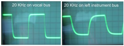
I analyzed the signal output on the bus and I found that it is altered on the left and right instrument buses compared with the remaining two buses (vocal and buss).
See the enclosed picture ... the square wave at 20KHz is very beautiful on the bass and vocal buses while it is deformed on the right-left instrument buses.
Is it normal?
Antonio
Attachments
1) Which are the 5K load you refer in the post n.150?
If you look at the bass tone control, at mid frequencies the two capacitors can be considered short circuits so the load is effectively R16 in series with R15 which totals just over 5K ohms.
2) Why below the 200Hz the tone control of bass becomes asymmetric? ...and how could it be eliminated ?
Looking at your results it seems the bass cut is as expected but the bass boost is only giving 5dB of boost. I think part of the problem is R17 which I think is much too low. I think it ought to be something like 10K ohms.
As to the output stage …
- I remember you that the mixer section is a passive one (see schematic)… and according to your calculation it should produce a loss of 20 dB.
- Due to the dual gang-pot and the realtive 47K on its wiper ... when that potentiometer is in the middle position, we have (in the worst conditions ... i.e. 10 mV after the input transf and tone control switched-on) 850 mV output on the left and right instrument bus versus 1091 mV on the remaining two buses (vocal and bass)...about 2 dB loss!
- The subsequent SRRP stage has a gain of 23 dB (or more).
- The output stage should drive cables that can also be 20-30 mt long.
1) Do you have some suggestion for the output stage?
2) How to solve the problem of different signal levels on the buses?
Ciao
Antonio e Francesco
I have no experience of driving audio signals along 30m of cable but clearly you should aim for a low output impedance and the ability to drive a capacitive load (at 100pF per metre, a 30m cable is like a 3nF capacitor). You could use an SRPP stage again but use a different tube running at a higher current - and ECC99 running at around 16mA might work or alternatively the White Follower is supposed to have a very low output impedance.
For the different signal levels on the buses the easiest solution is to increase the gain of mix amplifier SRPP by bypassing its bottom cathode resistor.
Cheers
Ian
Ian,
I analyzed the signal output on the bus and I found that it is altered on the left and right instrument buses compared with the remaining two buses (vocal and buss).
See the enclosed picture ... the square wave at 20KHz is very beautiful on the bass and vocal buses while it is deformed on the right-left instrument buses.
Is it normal?
Antonio
Yes, it is normal. It indicates a high frequency roll off, probably in the region of 60KHz. I have attached a paper that describes the various effects of frequency response upon a square wave.
Cheers
Ian
Attachments
Ian,
we are still searching for an output tube buffer stage. The main points in discussion are:
1) Should we use a balanced output ? We believe ...yes.
2) What kind of unbalanced-balanced transformation device is better? ... a transformer stage or a tube stage?
3) Which values of output impedance and output current we have to select?
Which type of output buffer stage will you use with your mixer?
Ciao
Antonio e Francesco
Summin amp for mixer section other
Hi
This is gEorge
GridLeak.blogspot.com has the start of a blog about vintage tube gear I have restored, while trying not to go crazy doing it
Pictures by SalesBoy - Photobucket has some of the tube preamps I have built on it
I have built also, five and seven band tube EQs, Neve frequencies, that use 12db/octave filters, and a summing amp to mix the pure and the +- bandpass signals from the filters.
Some advice.
A. Forget triodes of any type in the 1st. stage of a mike or high gain preamp
12ax7 has a voltage gain max of 100
EF86, 5879, 39/44, 6sj7 and other pentodes have voltage gains up to 750, so they are loafing at the VGs that triodes have to really stretch to do, and super quiet to boot.
Other tubes, completely unused now days, and super tubes for preamps are,
6an8, 6gh8. 6bl8, 6u8, are 9-pin, pentode/triode tubes, that are super for 1st. and buffer stage, negative feedback to the Kathode of the pentode, or to the bottom side of the secondary of the in trans.
The pentode has acres of quiet and with 6gh8 and 6bl8 tubes, very musical sonics as well. Much more pretty sounding than 12ax7 or 12au7 tubes.
I have also built/restored many preamps with the older 6sj7, 39/44, #78, and other pentodes that have acres of quiet, smooth gain.
You also need a real negative feedback gain control, or you end up using pad all the time if the 1st. stage can not swing a lot of level.
Pad kind of kills the sound, the dynamics of it, so less pad is best.
One trick is to "Float" the secondary of the in trans, make it the center between a resistor to ground, and a resistor to the grid, and then put audio back to the bottom side of the trans, as gain
The 9-pin tubes can allow you to make smaller channel strips
B. I had to have a summing amp for the five and seven band EQs, so I played with a 12au7, and came up with a correct summing amp, negative feedback to the summing resistors so there is no cross effects from one input to another as a true summer.
i think the summ resistors were 51K and neg back like 220 K
I can dig up the files and post the circuit
I am saying that, yes you can make a true summer with a 12au7 triode, that is low to zero gain, low Z out, and quiet.
C. I did a lot of tests to measure what tubes would drive the lowest Z, in basic triode mode, and some as Mu stage.
There are a few very low plate impedance tubes, and that is one of the most critical values of a tube needed for it to drive low loads.
12b4 has a plate impedance of 1000 ohms and will drive loads down to 600 ohms easy.
I have also circuits for 12au7 running on around 150v+ that will drive down to 600 ohms, about 8v rms clean.
So you might be able to get rid of the tl082 as a buss driver, and go tube.
Helps to look at old tube PA amp circuits to see how they summed and the gain stages with older tubes, and the pentode/triode tubes like 6gh8 a etc.
I had to build a few phono preamps a while back, and decided to use two 6an8s instead of the usual 12ax7 deal. The stereo phono preamps were much quieter, and the 6an8 tubes much more musical sounding.
Ian,
we are still searching for an output tube buffer stage. The main points in discussion are:
1) Should we use a balanced output ? We believe ...yes.
Since you are running long lengths of cables in a potentially harsh environment I would agree that you should run balanced but only if the device at the other end of the cable has a balanced input.
2) What kind of unbalanced-balanced transformation device is better? ... a transformer stage or a tube stage?
I am not aware of any balanced tube only output stages. I would recommend using a transformer.
3) Which values of output impedance and output current we have to select?
You should aim for as low an output impedance as possible and as much current capability as is necessary to drive the load. The big question is what is the load?
Which type of output buffer stage will you use with your mixer?
My mixers are not designed to drive 30m of cable or 600 ohm loads. They will drive several metres of cable and a 10K load. For these I use a 6CG7 mu follower running at about 5mA. To convert to a balanced output I use a Sowter 600:600 output transformer.
Cheers
Ian
I don't want to start an argument or be controversial but I have to say that I cannot agree with some of ElectricMan's advice.
A. Pentodes do have a theoretical mu (gain) of many hundreds but it can never be realised in a practical circuit. With an EF86 for example, the best you can get is 200 and that is with a 400V supply and 220K plate resistor. With normal supply voltages and plate resistances, you will struggle to get over 100. Even then, with the output impedance is much higher than a triode so as soon as you load it with the next stage and some NFB the gain you actually get is much lower.
Pentodes are not super quiet. Pentodes are in fact several times noisier than triodes due to partition noise.
You do not need negative feedback gain control. it is easy to design a first stage with sufficient swing to be able to handle all the required input levels with a single switchable pad.
I have never seen any evidence that a "pad kind of kills the sound, the dynamics of it". If you have some ElectricMan please share.
B. Please post the circuit of your 12AU7 based summer with "negative feedback to the summing resistors so there is no cross effects from one input to another as a true summer"
Cheers
Ian
- Status
- Not open for further replies.
- Home
- Live Sound
- PA Systems
- Tube mixer