Oliver,
What is the maximum current you can extract from this Shunt Regulator? Maybe there is no max as long as I make the heatsink bigger and lower my current adjust resistor ? I read through the thread, maybe I missed it.
Thanks,
Joe
What is the maximum current you can extract from this Shunt Regulator? Maybe there is no max as long as I make the heatsink bigger and lower my current adjust resistor ? I read through the thread, maybe I missed it.
Thanks,
Joe
Hi Joe,Oliver,
What is the maximum current you can extract from this Shunt Regulator? Maybe there is no max as long as I make the heatsink bigger and lower my current adjust resistor ? I read through the thread, maybe I missed it.
Thanks,
Joe
here is Salas answer to your question:
The answer is that its a matter of dissipated power and conduction to nearby PCB components until several tempcos will be running away, we haven't tested the power roof in its thread. I think that up to 20-30W dissipation has been tried with the earlier BJT ref version on an amp, and got deemed impractical in the long run due to the heated environment from the nearby valves not helping. If the main body of consumption goes to the load, only the +20-30mA necessary set difference can be constantly burning though, and be very safe.
Oliver,
I powered up the DAC, 4:1 MUX S/PDIF using the Placid and LCDPS power supplies first and everything worked fine using the Avel Lindberg toroidal transformers. I then powered down and hooked up the 2 R-Cores that TFan69 and a few others were using. When I powered up the DAC and Tubeizator boards using the Salas HV Shunt. One HV shunt seemed fine, but the other smoke immeriately came from (I believe the 9610 Mosfet or the BZX55C12 Zener). Also, the ceneter LED blew about 10 seconds into the power up. Plus the 56K (R1) resistor sparked. I immediately powered down. And then noticed the other R-core transformer was so hot it was melting the plastic cover surrounding the wires. The Shunt board didn't spark or blow or smoke at all, only the other shunt did. The R-core for the sparking, smoking board seemed to be a normal temperature though. I do not think that the wiring was incorrect on either R-core. And as I said, the other Twisted pear boards, toroid transformers and power supplies seemed fine. They don't get overly hot, smoke, etc.
I did not have time to take any measurements on the HV shunt boards to know how much voltage and current were going through them. Do you (or anyone else) know why the Salas HV shunt would have had these problems on one but not the other, while the R-core of the non-smoking shunt board was overheating? I could use some help and guidance. Thanks for your help.
Greg
Last edited:
Oliver,
I powered up the DAC, 4:1 MUX S/PDIF using the Placid and LCDPS power supplies first and everything worked fine using the Avel Lindberg toroidal transformers. I then powered down and hooked up the 2 R-Cores that TFan69 and a few others were using. When I powered up the DAC and Tubeizator boards using the Salas HV Shunt. One HV shunt seemed fine, but the other smoke immeriately came from (I believe the 9610 Mosfet or the BZX55C12 Zener). Also, the ceneter LED blew about 10 seconds into the power up. Plus the 56K (R1) resistor sparked. I immediately powered down. And then noticed the other R-core transformer was so hot it was melting the plastic cover surrounding the wires. The Shunt board didn't spark or blow or smoke at all, only the other shunt did. The R-core for the sparking, smoking board seemed to be a normal temperature though. I do not think that the wiring was incorrect on either R-core. And as I said, the other Twisted pear boards, toroid transformers and power supplies seemed fine. They don't get overly hot, smoke, etc.
I did not have time to take any measurements on the HV shunt boards to know how much voltage and current were going through them. Do you (or anyone else) know why the Salas HV shunt would have had these problems on one but not the other, while the R-core of the non-smoking shunt board was overheating? I could use some help and guidance. Thanks for your help.
Greg
😱
That looks to me like a heavy short... I will additional ask Salas, if he had such a problem.
Let´s start to check everything from the beginning.
1st look if every part is in the right direction (diodes & caps).
2nd measure if the diodes and the caps have no short
Report back if you have done this.
Because I am not sure I got it right, was everything high voltage side working OK with the toroidals, but it did not with those R-Cores? Or it wasn't tested before? If it wasn't, I would troubleshoot the orientation of MJE 350s first and all parts, change the smoked parts, the 9610, and remove all zeners. Then I woud measure the R-Cores with no connection for what they give on those wires. Would use a fuse to the rating that each one R-Core has on its label. If this is the typical Tubizator application, I don't see what could be new than those R-Cores or possible errors in parts values and orientations/assembly in the HV regs, since this is a well repeated project as I gather here.
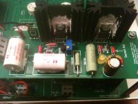
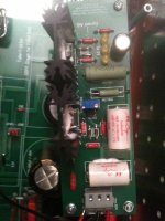
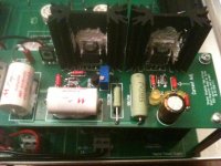
OK, I double checked the orientation of everything on the Salas Shunt board (I double checked when I soldered them in as well) and everything appears to be soldered in OK. I posted some pictures so you can see for yourself. I really don't think it's a short due to orientation of parts. Both boards have identically oriented parts. As I saind, one board was fine and the other had the blown LED, and smoke coming from the 1R resistor and I believe the 9610 Mosfet. Also, on the tubeizator board itself the 1K resistor started smoking. This is on the tubeizator board with the problem shunt board. I forgot to add that part in the last post. Check the pics and see if they look OK to you. I will have to rewire the R-Cores up again to test them and see what voltage and amperages are coming out of them. I will repost after I do.
Greg
Greg
Attachments
and smoke coming from the 1R resistor and I believe the 9610 Mosfet.
Witch 1R resistor?
Because I am not sure I got it right, was everything high voltage side working OK with the toroidals, but it did not with those R-Cores? Or it wasn't tested before? If it wasn't, I would troubleshoot the orientation of MJE 350s first and all parts, change the smoked parts, the 9610, and remove all zeners. Then I woud measure the R-Cores with no connection for what they give on those wires. Would use a fuse to the rating that each one R-Core has on its label. If this is the typical Tubizator application, I don't see what could be new than those R-Cores or possible errors in parts values and orientations/assembly in the HV regs, since this is a well repeated project as I gather here.
That's correct Salas. Everything from the Placid shunt and LCDPS Twisted Pear boards worked fine with the oroids. It was with your shunt/tubeizator and the R-Cores that the problems occured. I believe the parts used and their orientations are correct on both of your HV shunt boards. I think it has to do with the R-Cores personally, but I may be mistaken.
OK Oliver, I tested all diodes and caps. The only problem I had with the testing was with the 25V 100uF Nichicon cap on the smoked board. I could not get a reading with the one on the board that blew the LED and smoked. I did not desolder either of the leads which may have something to do with it. I have not tested very many capacitors, so perhaps I am testing it incorrectly? I do have the correct polarity with the Ohm meter though. All other caps and diodes were not shorted. The Nichicons are oriented correctly as far as I see. Don't know why the Nichicon would be a problem?
Greg
Last edited:
You need to check the R-Cores first. Another weird thing is that you got two HV regs that each one has shown different behaviour. One sparked and flashed LED, the other just had its Tx hot. Should have had the same failure mode if the R-Cores are identical and the regs assembly is identical.
P.S. Are you sure that the grounding is OK? There is a single common ground terminal pin between DCin/out on those DVB HV boards. Is that 3pin terminal getting all the correct wires it should? Also can by any chance those zeners be diodes sold by mistake? You wrote maybe one smoked. Take them all out. Both the little glass ones and the bigger black one behind the 9610, next time you test.
P.S. Are you sure that the grounding is OK? There is a single common ground terminal pin between DCin/out on those DVB HV boards. Is that 3pin terminal getting all the correct wires it should? Also can by any chance those zeners be diodes sold by mistake? You wrote maybe one smoked. Take them all out. Both the little glass ones and the bigger black one behind the 9610, next time you test.
You need to check the R-Cores first. Another weird thing is that you got two HV regs that each one has shown different behaviour. One sparked and flashed LED, the other just had its Tx hot. Should have had the same failure mode if the R-Cores are identical and the regs assembly is identical.
P.S. Are you sure that the grounding is OK? There is a single common ground terminal pin between DCin/out on those DVB HV boards. Is that 3pin terminal getting all the correct wires it should? Also can by any chance those zeners be diodes sold by mistake? You wrote maybe one smoked. Take them all out. Both the little glass ones and the bigger black one behind the 9610, next time you test.
I believe that's part of the problem Salas. I believe the R-Cores are not made very consistantly which is why some people get a reading of 198 V and others get (something like 270V) from the same transformer type (R26-90).
As far as grounding goes, I have all 3 wires hooked into the terminals on the HV boards. The ground goes to the ground on the relay 1. The are both wired the same and correctly (I double checked with Oliver's pictures before I powered up the HV shunt boards and Tubeizators).
Greg
P.S. Also, Nevermind about the capacitor on the smoking board being bad. I got a reading from it. It's not shorted. As far as I can tell, nothing is shorted and all is oriented correctly.
Last edited:
I remember TFan69 he wrote all his ''ghost in the machine'' problems vanished when he got rid of those R-Cores, they are suspect no1, still be thorough, go step by step and check everything. First step is verify the transformer wires you use for what they give without being connected/loaded. Watch it, the voltage is high.
I remember TFan69 he wrote all his ''ghost in the machine'' problems vanished when he got rid of those R-Cores, they are suspect no1, still be thorough, go step by step and check everything. First step is verify the transformer wires you use for what they give without being connected/loaded. Watch it, the voltage is high.
OK Salas. I will have to rewire the transformers up to test them. I was planning on just buying custom transformers from a place in Chicago, Illinois. I will test the R-Cores I have to see what Voltage is being given. Thanks for the help.
Greg
Good luck and be careful when verifying/testing everything HV, from trafos to connections & PCB checks.
Hi Oliver,
Which Schematics did you use for the HV Shunt Regulator?
I tried this link:http://www.diyaudio.com/forums/power-supplies/134801-simplistic-mosfet-hv-shunt-regs.html
But it has different components value. Can you please direct me to that schematics as I need to troubleshoot my Shunt Reg. I accidentally shorted the output and ground with my test clip and now I'm getting the same voltage on input and output of the Regulator. Most likely I blew up one of the transistor.
Thanks,
Joe
Hi Oliver,
Which Schematics did you use for the HV Shunt Regulator?
I tried this link:http://www.diyaudio.com/forums/power-supplies/134801-simplistic-mosfet-hv-shunt-regs.html
But it has different components value. Can you please direct me to that schematics as I need to troubleshoot my Shunt Reg. I accidentally shorted the output and ground with my test clip and now I'm getting the same voltage on input and output of the Regulator. Most likely I blew up one of the transistor.
Thanks,
Joe
Check first IRF9610🙂
OK, I hooked up the 2 R-core transformers and the results from the one that didn't overheat and fry stuff on the HV shunt board were:
165V, 0.1A: Actual reading was 206V
9V, 1A : Actual reading was 11.33V
The R-core that fried the HV shunt board had the reading of:
165V, 0.1A: Actual reading was 77V!!
9V, 1A: Actual reading was 12.28V
The overheating R-core actually is a step down transformer instead of a step up on the 165V, .1A lead(s).
If it was putting out 77V instead of 165 or 207V, wouldn't the amperage probably be way higher than 0.1A?? This is probably why it fried the components on the board , right? What do you guys think?
Greg
It could have been putting out way more than the other one when it did the job before it went broken by its own heat, now outputting low. The filament secondary will torture heaters regs by being high in both.
Good point Salas. Whichever way it was, was obviously too much for the HV shunt board. The R-core still overheats. It gets too hot to touch in about 3 minutes, while the other R-core feels cool even after 30 minutes. I have the other parts to put onto the HV shunt board that was fried. I will hopefully get the custom R-cores soon and all should be well.
Greg
Greg
- Home
- Group Buys
- Tube-I-zator Professional PCB