I like it all, (particularly the handle).
Before I go back through the thread myself, have you collected a single schematic of the amp, as built?
Before I go back through the thread myself, have you collected a single schematic of the amp, as built?
Thanks! I think this is the one I used: Richelieu Contemporary Metal Pull - Brushed Nickel - 96 Mm C. To C. | The Home Depot CanadaI like it all, (particularly the handle).
Good point, I haven't. I think I have pieces of it in a couple of different LTSpice sims, but not the whole thing. You're right, I really should pull them together before I forget what I built.Before I go back through the thread myself, have you collected a single schematic of the amp, as built?
-Gnobuddy
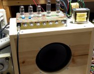
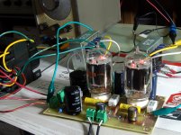
Looks great, love the handle, and the bare bones controls. Plug and play.Here are some pictures to wrap up the project (building a guitar amp for a senior-citizen friend, on a tight budget.)
I've done some further experimenting with the KMG gain stages.
First, I was getting annoyed with the B+ fluctuating with the line voltage.
So I decided to make a simple series pass voltage regulator.
I had some 75v zeners laying around, so 4 of them would be good for the desired 300V.
I used an IRF820 as the pass element. I included a 1k gate stopper. It seemed to work.
Did well with a 20mA load, which is way more than what I intend to use.
Good, now I don't need to keep adjusting the variac to get 300V.
I made a perfboard module containing the LND150, the 1k and 180R resistors and the 6 diodes. This mounts a couple inches away from the breadboard and has 3 leads, which can be considered "plate", "grid", and "cathode." This frees up a lot of space on my rather small breadboard. Plus it prevents confusion.
So I tested the module with the new regulated supply. Works perfectly. So I build a second module. I wanted to test if two gain stages could operate off the same +3V fixed bias rail.
First, I connected the output of the 1st stage to the input of the 2nd with a simple 470k/470k voltage divider. Of course there's a 22n cap off the "plate" of the first stage.
Everything's looking good. Behaves as expected.
Next, I put the standard Fender TMB tonestack, with volume control, in between the two stages. Fired it up, looked at the output on the scope, then started twiddling with the knobs.
Here's where things got ugly. When the treble control and volume control were turned past 7, I got some horrible oscillation.
Not just a little fuzz on the tips of the sine wave, we're talking full blown berserk mode.😱
I've seen the same problem in one of my cheapo valve amps where I added a gain stage and the Fender stack. In that amp, the issue was resolved by star grounding everything.
With that in mind, I attacked the problem from a layout/grounding perspective.
Wrong!🙁
Some of you have already figured out the problem, and I should have known better, but sometimes when you're in the heat of battle you don't think too clearly.
It wasn't grounding, It wasn't the layout, there wasn't any kind of positive feedback in the +3V rail.
Of course it was the regulator.
When I removed it, and went back to the variac method, the circuit worked fine.
That should have been the first thing I did, true.
But I guess I got a false sense of security with the voltage regulator because up till now it performed perfectly.
Next, I looked through my parts bins and discovered some TIP50 npn.
So I removed the IRF820 and put in a TIP50.
Presto, no more oscillation. Twiddle that treble knob all you want. Crank the signal generator up to 100kHz, crank signal generator up to 10Vpp signal - solid.
I would have gone with the TIP50 in the first place, but I forgot I had any.
The moral of the story:
Don't use mosfets as pass elements in high voltage series regulators.
Especially when you are breadboarding and there are long leads flying all over the place.
Another word of advice:
If you are breadboarding, and you have a metal plate to hold your pots, be sure to ground that plate! Otherwise it picks up all kinds of stray junk and makes your signal look wobbly.
Next: I need to add another KMG gain stage.
Then reduce the signal to feed into a graphic eq, which will go into a power amp and speakers. Figure out which frequencies need to be cut or boosted. Then build a de-nastifying circuit.
Will need to built the voltage regulator on perfboard, to gain more space on breadboard.
Oh yeah, and at some point actually plug a guitar into it!🙂
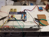
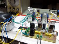
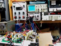
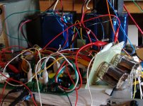
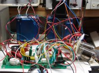
Here's a photo of what I've got so far. The isolation transformer is on the far right, the voltage doubler is built on the terminal strips. The regulator is on the right half of the breadboard, the LND150 modules are above the left side of the breadboard. The metal plate, cut from an old computer case, holds the pots. You can see the breadboard is rather small, but it's what I've got. Yes it's all mounted on a piece of wood. The signal generator, scope, variac and other equipment are off camera.
Attachments
Interesting! I guess sometimes an old slow part is better than the new uber-fast one, eh? 🙂So I removed the IRF820 and put in a TIP50. Presto, no more oscillation.
I made exactly that mistake, and the amp in question hummed and buzzed even though I had tried to be very careful with layout. Finally I touched the metal plate, probably by accident, and the amp went quiet. Aha!If you are breadboarding, and you have a metal plate to hold your pots, be sure to ground that plate!
In my case, the plate was aluminium, so I couldn't solder to it (actually you can, with zinc solder and special flux, but both those tend to contaminate the soldering iron quite badly, making it useless for regular soldering afterwards.)
A star-washer and a couple of nuts is working okay so far, but I fret about oxide formation bringing back the hum one day.
Thanks for the progress report, looking forward to reading more of your KMG adventures!
-Gnobuddy
If you are breadboarding, and you have a metal plate to hold your pots, be sure to ground that plate! .......I made exactly that mistake, and the amp in question hummed and buzzed
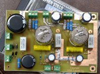
Even if you don't have a metal plate.......note the ground wires running to each pot. If you have 4 gain stages, it will find a way to buzz.....and sniff out the fluorescent light fixture overhead....
Attachments
It's kind of like those silly audiophool op amps. They can be really fussy about layout and power supply decoupling. A lot of work and expense for something that I can't tell the difference compared to a cheap 5532, which work fine in my high end breadboard.🙄Interesting! I guess sometimes an old slow part is better than the new uber-fast one, eh? 🙂
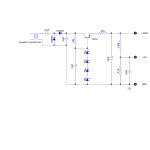
I've attached the power supply/regulator schematic I am using.
The capacitor values were chosen kind of arbitrarily based on what I have in stock.
I had a couple of 33uf /450v so I stuck those in there. The 10R resistor is there because the schematic I copied has it. I think it's supposed to protect the transistor in case of a momentary short circuit, but I don't know about that.
I could add a transistor across this series resistor for a current limiter. If I bump up the series resistor to 22 ohms, it should limit current to 27ma. More than I plan on using, giving plenty of margin, but low enough to (hopefully) protect the TIP50 in case of a slip of a voltmeter probe or something.
I'll have to see if it's going to need some RC decoupling as I add more gain stages. KMG's design uses RC decoupling but doesn't say if he's using a regulated supply. He was trying to be true to the original JCM800 valve amp, but I just want something that sounds good.
I'm really quite surprised this high voltage stuff works in this type of breadboard. There's no way these things are rated for 300+ volts, probably more like 30.
I try to space things out at least 2 rows, but there's some places where you can't avoid having to use the adjacent row.
It is quite an adventure sticking a scope probe in there, with some of the component leads sticking up with 300v on them.
Attachments
Funny thing, I remember having no hum problems from the pots alone, even with pot housings not grounded. Initially I made a thin plywood front panel while I prototyped stuff, and since there was no hum issue, I mentally checked off the question mark next to "Ground pots?"Even if you don't have a metal plate.......note the ground wires running to each pot.
After that, I forgot all about grounding the pots or front panel.
Later I made a temporary aluminium front panel, about 21" long and 2" wide (because a local store carried 2" wide Al strips). That's when the buzz and hum started. I guess 42 square inches of antenna picks up a lot more interference than a pot housing alone!
I have no trouble believing that! 😀If you have 4 gain stages, it will find a way to buzz.....and sniff out the fluorescent light fixture overhead....
Anyone know if contemporary LED lights or compact fluorescent bulbs cause amps to buzz? I'm guessing not, the switching frequencies are probably far above the audio band.
-Gnobuddy
I have a piece of plywood which I have pots mounted on a piece of aluminum, breadboard mounted in the middle, an assortment of tube sockets on the other side on another plate, a couple relat bases to hold octals and to the right a terminal strip to attach the transformer, rectifiers and power supply caps. Also an important sheet of aluminum that sits under the plywood to act as a ground plane. Not perfect but it allows me to throw something together pretty quick.
I'm real excited about your progress with the circuit and it makes me want to clean off a section of the bench to play. But I am being strict with myself. I spent most of the afternoon carving a neck and I might be able to get all the shaping done tonight. Then side dots and maybe fretboard markers. The body is ready for finish so the neck is holding things up. This is going to be the largest guitar I made, have some bodies made but no necks for them yet. But this is a special guitar like no other. Mainly built out of one 2"x4".
I'm real excited about your progress with the circuit and it makes me want to clean off a section of the bench to play. But I am being strict with myself. I spent most of the afternoon carving a neck and I might be able to get all the shaping done tonight. Then side dots and maybe fretboard markers. The body is ready for finish so the neck is holding things up. This is going to be the largest guitar I made, have some bodies made but no necks for them yet. But this is a special guitar like no other. Mainly built out of one 2"x4".
...I'm really quite surprised this high voltage stuff works in this type of breadboard. There's no way these things are rated for 300+ volts, probably more like 30...
36V. 2A or 1.5A. A couple have datasheets; try DigiKey.
Clearly the "36V" is conservative. Much thinner plastic on transformer wire has been known to take 300V long enough to expire the warranty. However 300V out in the open with fingers poking at it is riskier.
_I_ would prefer a breadboard. Nice pine board, tag-strips, screws. If nothing else, it looks dangerous, thus gets some respect.
Some really good ideas there, I might steal a few of them. Thanks for sharing.I have a piece of plywood which I have pots mounted on a piece of aluminum, breadboard mounted in the middle, an assortment of tube sockets on the other side on another plate, a couple relay bases to hold octals and to the right a terminal strip to attach the transformer, rectifiers and power supply caps. Also an important sheet of aluminum that sits under the plywood to act as a ground plane.
And good luck with that guitar!
-Gnobuddy
I've taken to building straight onto 3/8" thick plywood. Valves, transformers, big caps on top, resistors and small caps on the bottom, tie-points made with 1/4" long #4 brass wood screws and placed wherever needed for best layout._I_ would prefer a breadboard. Nice pine board, tag-strips, screws.
This is reasonably quick for prototyping if a lot of parts tinkering is not going to be necessary, and durable enough to also be the finished product. I hate doing the same thing twice.
When done, the board mounts on stand-offs on a grounded metal sheet ($4 baking pan from the dollar store), with a sheet of insulator in between just in case ($1 plastic cutting board, also from the dollar store.)
-Gnobuddy
Anyone know if contemporary LED lights or compact fluorescent bulbs cause amps to buzz? I'm guessing not,
I spent half a day chasing "oscillation" in a tube amp breadboard, the sucky kind that comes and goes when you touch things. The scope showed it on the output and the distortion readings changed considerably as I poked my finger around in a live amp, one that was running on over 500 volts....then it dawned on me that I had recently swapped out the fluorescent shop lights for some fancy LED shop lights from Sams club. Sure enough the oscillation vanished as soon as the lights were switched off.
I have noticed that there are several things that will make small but repeatable changes in the distortion measurements on a clean tube HiFi amp. Distortion in the under 0.1% kind of clean. The shop lights will double that reading, and I can get it up to 0.5% by poking around with my finger. The LED light bulbs in the fixtures in the basement ceiling seems to have an effect sometimes......the mystery as to the higher distortion readings at night has been traced to the 4 year old low budget Walmart black Friday 65 inch Visio TV in the room above my workbench.
I have not noticed any difference in the sound quality in the HiFi amp playing real music through speakers with or without the LED shop light on, but it DOES raise the noise level in my high gain 4 tube guitar amp when the all the knobs are turned up full. The $50 swap meet Squier Strat is worse case, but it's rather noisy and poorly made to begin with......I traded a big box full of tubes for it.
The noise is not really a buzz, but there is some 60 / 120 Hz content in it, more like a modulated hiss.
I guess this is a general problem of vintage tube designs. Compared to modern semiconductors with SMD parts, physical dimensions are much bigger, the wiring of a tube amp is a bunch of antennas. Consequent electro-statical screening might help in your case, as does in electrical guitars as well.
We can do something about the wiring outside the valve (keep it very short, etc). But there are also all these inches of wire and square inches of metal plate inside the glass bottle, nice little antennae that we can't do anything about!the wiring of a tube amp is a bunch of antennas.
(Okay, we can slip grounded metal shields over our 12AX7s, if we don't mind them getting a bit hotter. But those of using oddball preamp valves won't find ready-made shields for them.)
This issue of internal antennae came to my mind some years ago when I read a few Internet posts by people attempting to make a complete guitar amp out of one single 6AF11, a three-tube compactron containing two triodes and one power pentode all in the same glass envelope. Most of these attempts failed, because with the output anode within a couple of centimeters of the input stages in the same bottle, feedback and oscillations were a chronic and virtually unsolvable problem.
For my own builds, somewhat to my surprise, so far I've gotten away with the components flat on the underside of the plywood "circuit board", and a ground plane a few millimeters below that. It probably helps that I don't build very high gain amplifiers.
-Gnobuddy
This issue of internal antennae came to my mind some years ago when I read a few Internet posts by people attempting to make a complete guitar amp out of one single 6AF11, a three-tube compactron containing two triodes and one power pentode all in the same glass envelope. Most of these attempts failed, because with the output anode within a couple of centimeters of the input stages in the same bottle, feedback and oscillations were a chronic and virtually unsolvable problem.
-Gnobuddy
And don't forget the pentode/power pentode tubes. Anybody want some 6T10's?
My HiFi amp breadboard is probably near worse case for being a receiving antenna. It contains mosfets and tubes and is spread out over about 4 square feet of bench space with long unshielded leads to the power supply and test equipment. I was also dealing with very low (for a tube amp) levels of distortion.
Hey, I was the idiot that tried to wire TWO of them together in P-P. (post #1362)
Some tubes like the 6AF11 were designed with a certain application and maybe even a general pinout in mind. We did the same thing with our IC chips. They were never intended to be wired up in a different manner.
Sometimes, there is a whole family of tubes that can't be used in what I would consider an obvious manner. Consider the 9AE and 9DC triode - pentode tubes (6BL8, 6GH8, 6EA8...). Originally intended for TV sets, they wound up in everything including some relatively popular HiFi sets (Scott used the 6BL8). Pick one of these with a high Gm pentode like the 6HL8 or 6MQ8 and use that pentode to drive the triode with both configured as gain stages.....TV jammer time! I was trying to use the pentode for an input stage, the triode for driving the tone stack, then the reverse with a second tube. It made about 2 watts on the bench, but flat out oscillated as soon as the guitar was plugged in. Cable alone, OK. Any guitar, even with the volume all the way down, oscillation city. I gave up on that one during the HBAC, but didn't want to mention it due to the then $1 tubes.
When I started out building amps in the 60's I screwed 3 or 4 octal tube sockets and a dozen of so terminal stripe to a pine board. Components were tack soldered between the sockets and strips with an old beat up soldering gun a neighbor gave me. Most of the tubes used had very low Gm which kept oscillation away, but there was a 5 KW AM radio station about a half mile from my house and some 130 KV power transmission likes across the street.....hum and "elevator music" were always a problem.
Sometimes you just have to try something that "can't possibly work" to see what happens. Sometimes it will surprise you by working very well. Can you take the PC board for a stereo SE HiFi amp, and connect a pair of compactrons in place of the driver and output tubes on the PC board entirely using clip leads, Even the OPT's were wired with clip leads. No "that can't possibly work" it will oscillate. Well It didn't.
After being pleasantly surprised, I distilled the "furball" down to a PC board. It made about 2 watts with the small dual triode tubes, 5 watts with the small triode - pentodes in UL, and about 9 with the big triode - pentodes in UL.
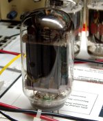
What do you do when you find a tube with a crack running up the entire side of the tube, but a good getter......you "test" it to see if you can break it! I had my power supply to 500 volts and that poor tube just kept cranking. I was getting about 12 watts of reasonably clean audio out of it.....and a good bit of red light when the drive was removed (worse case on a class A amp).
The details are here:
Spud anyone?
people attempting to make a complete guitar amp out of one single 6AF11
Hey, I was the idiot that tried to wire TWO of them together in P-P. (post #1362)
Some tubes like the 6AF11 were designed with a certain application and maybe even a general pinout in mind. We did the same thing with our IC chips. They were never intended to be wired up in a different manner.
Sometimes, there is a whole family of tubes that can't be used in what I would consider an obvious manner. Consider the 9AE and 9DC triode - pentode tubes (6BL8, 6GH8, 6EA8...). Originally intended for TV sets, they wound up in everything including some relatively popular HiFi sets (Scott used the 6BL8). Pick one of these with a high Gm pentode like the 6HL8 or 6MQ8 and use that pentode to drive the triode with both configured as gain stages.....TV jammer time! I was trying to use the pentode for an input stage, the triode for driving the tone stack, then the reverse with a second tube. It made about 2 watts on the bench, but flat out oscillated as soon as the guitar was plugged in. Cable alone, OK. Any guitar, even with the volume all the way down, oscillation city. I gave up on that one during the HBAC, but didn't want to mention it due to the then $1 tubes.
somewhat to my surprise, so far I've gotten away with the components flat on the underside of the plywood "circuit board"
When I started out building amps in the 60's I screwed 3 or 4 octal tube sockets and a dozen of so terminal stripe to a pine board. Components were tack soldered between the sockets and strips with an old beat up soldering gun a neighbor gave me. Most of the tubes used had very low Gm which kept oscillation away, but there was a 5 KW AM radio station about a half mile from my house and some 130 KV power transmission likes across the street.....hum and "elevator music" were always a problem.
Sometimes you just have to try something that "can't possibly work" to see what happens. Sometimes it will surprise you by working very well. Can you take the PC board for a stereo SE HiFi amp, and connect a pair of compactrons in place of the driver and output tubes on the PC board entirely using clip leads, Even the OPT's were wired with clip leads. No "that can't possibly work" it will oscillate. Well It didn't.
After being pleasantly surprised, I distilled the "furball" down to a PC board. It made about 2 watts with the small dual triode tubes, 5 watts with the small triode - pentodes in UL, and about 9 with the big triode - pentodes in UL.
What do you do when you find a tube with a crack running up the entire side of the tube, but a good getter......you "test" it to see if you can break it! I had my power supply to 500 volts and that poor tube just kept cranking. I was getting about 12 watts of reasonably clean audio out of it.....and a good bit of red light when the drive was removed (worse case on a class A amp).
The details are here:
Spud anyone?
Attachments
-
 Cracked.jpg169 KB · Views: 100
 -
 Spud_Amp_2.jpg296.3 KB · Views: 101
 -
 Small_tubes_1.jpg287.2 KB · Views: 87
 -
 PCboard.jpg318.2 KB · Views: 189
 -
 Working_Setup.jpg336.4 KB · Views: 195
 -
 Furball_operational.jpg331.6 KB · Views: 195
 -
 Furball_board.jpg324.5 KB · Views: 191
 -
 Furball_3.jpg337.2 KB · Views: 193
 -
 500volts_signal.jpg351.8 KB · Views: 92
I built a 3rd KMG "triode" module.
Here, I found some differences due to component variation. The other 2 modules bias up to 195-200V on the plate. This 3rd one was only about 175v. I measured the diodes with the multimeter diode checker. The UF4007 and BAT85s were the same as the other two modules, but the 1N914 measured 0.644v. The "good" modules measured closer to 0.600v. So I replaced the "bad" 1N914. Now the "plate" voltage is 196v, close enough.
Once that was done, I added it to the existing circuit. The idea is the 1st and 2nd stages match the fender blackface preamp. The 3rd stage is not for reverb mixing, but is intended to be overdriven when the controls are cranked up.
Next, I checked the gain of each stage. Keep in mind, I don't have one of those fancy digital scopes, so I have do the measurements the old school way. So give or take 5%.
Each stage is 100k "plate", 1k5 "cathode", bypassed by 10uf, no resistor in series with the bypass cap. Fender used 25uf, I prefer 10, and sometimes less on the first stage. Personally I find the standard fender preamp too bass heavy.
The fixed bias is derived from a 270k/2k7 voltage divider filtered with 10uf, gives +3v.
I set the signal generator for 100mVpk @500hz.
The first gain stage is heavily loaded by the tone stack. At the "plate", a 5Vpk signal, so gain of 50.
The tone stack/volume is set to all controls at midpoint. On the "grid" of the second stage, 40mVpk. The tone stack and volume control have knocked the signal down to less than half the original.
If I recall correctly, a Fender amp at this point will be closer to the original 100mVpk or even a little higher. However, Fender uses those 30% taper pots, I don't have any of those, I'm using the cheapo 10% taper ones. So tweaking the volume control a bit clockwise the voltage shoots way up.
I conclude this is reasonable behavior, probably close enough to the real thing.
The second stage is coupled to the 3rd, with a 22n to a 470k/470k voltage divider, so a load of 1Meg. Here we get a gain of about 120. This actually is pretty close to what LTspice predicts, around 111. For some reason my earlier experiments had lower gain into a 1Meg, but I could have made any number of mistakes🙁
The third stage is loaded with a 22n/1Meg, and the gain is similar to the 2nd stage, a little higher at 125.
With all controls dimed the third stage is pretty well overdriven and outputs 200Vpp or 100Vpk or about 70V RMS.
At this point I don't know if there's too much gain or not enough. There's certainly enough for clean tones, but it's unknown at this point what the overdrive is going to sound like. I'm not going for "Triple Rectifier" here, more like "cranked Champ." I can always reduce gain with series resistors on the "cathode" bypass caps. I can always get more gain with another stage, but would rather not.
For "rawk" tones, there's always the Stevie Ray Vaughn trick of using the Tube Screamer as booster.
Now I need to reduce the signal coming off the third stage.
Right now, for testing purposes, I'd like to go into a graphic equalizer which wants 1V RMS, at low impedance
The graphic will be used to help figure out what kind of "de-nastifier" I'm going to need. The graphic will go into the power amp, into bookshelf speakers.
KMG uses a source follower with 100k/10k voltage divider into a 1uf cap, into a 1Meg resistor to ground.
In this scenario, it would produce about 7V RMS, way too much.
If I replace the 1Meg resistor with a 1k pot, things look a little better.
I think it would be a good idea to put in a diode or LED clamp (RAT style) after the pot, just to make sure the voltage at this point doesn't get too high, particularly transients when the the preamp is powered on or off.
I'm open to suggestions on how to handle this.
After this is resolved, the next issue is the "de-nastifier" circuit.
I've decided this should be done at low voltage, with a separate power supply.
I can adapt Gnobuddy's de-nastifier and/or other cabinet simulator ideas, which are all low voltage designs.
So do many others. Stevie Ray Vaughan's Fender amps were modded with much lower value cathode bypass caps. Personally, I like 2uF or even 1uF for good tone balance, suitable for both S/C and H/B pickups.Each stage is 100k "plate", 1k5 "cathode", bypassed by 10uf, no resistor in series with the bypass cap. Fender used 25uf, I prefer 10, and sometimes less on the first stage. Personally I find the standard fender preamp too bass heavy.
Last edited:
- Status
- Not open for further replies.
- Home
- Live Sound
- Instruments and Amps
- Tube Emulation & EQ