In my experience, it's better to insulate pot shells from any petal plate, and then solder wire connections to each pot shell, with the wires going to a suitable preamp ground point.Interesting! I guess sometimes an old slow part is better than the new uber-fast one, eh? 🙂
I made exactly that mistake, and the amp in question hummed and buzzed even though I had tried to be very careful with layout. Finally I touched the metal plate, probably by accident, and the amp went quiet. Aha!
In my case, the plate was aluminium, so I couldn't solder to it (actually you can, with zinc solder and special flux, but both those tend to contaminate the soldering iron quite badly, making it useless for regular soldering afterwards.)
A star-washer and a couple of nuts is working okay so far, but I fret about oxide formation bringing back the hum one day.
-Gnobuddy
I think this may be caused by the 100k Zout of the MOSFET stage. Merlin Blencowe says a 12AX7 with the same 100k anode resistor has a Zout closer to 40k, because of the rather low internal resistance of a triode. So you can indeed expect about double the loading effect on KMG's MOSFET stages, compared to a real half-12AX7 stage.The tone stack and volume control have knocked the signal down to less than half the original.
Why not use a simple voltage divider with an attenuation ratio of around 200:1, say 470k / 2.2k? You get a low 2.2k output impedance, about 1 volt p-p output, and a guarantee that the output cannot exceed about 1.5V pp even if you drive 300 Vpp into the input.With all controls dimed the third stage is pretty well overdriven and outputs 200Vpp or 100Vpk or about 70V RMS.
<snip>
I'd like to go into a graphic equalizer which wants 1V RMS, at low impedance
I'm curious to hear your feedback on how you like (or dislike) the eventual result.The graphic will go into the power amp, into bookshelf speakers.
As you know, I tapped the output signal of my de-nastifier to create a mic level line-out signal which I fed to a small flat-response P.A. system. It sounded good to me, and very close to the actual acoustic sound from the amp's own speakers. I actually prefer the sound of the P.A. system, which doesn't have the slight boxiness of the actual guitar amp enclosure.
The P.A. system I used is an Acoustic AG30, a flat-response speaker (8" woofer, small dome tweeter) in a cabinet with the front face angled back at 45 degrees. It was designed for use with acoustic guitar, microphone (for vocals), keyboards, etc, and has a cleaner and more neutral sound than most "proper" P.A. systems. There is also far less of that boxy colouration than most speakers have, probably because of the heavily angled front panel.
-Gnobuddy
If you believe the ampbooks online calculator, a 2.2 uF cap results in a -3 dB frequency of about 80 Hz, just about what the doctor ordered for an electric guitar in standard tuning.Personally, I like 2uF or even 1uF for good tone balance, suitable for both S/C and H/B pickups.
Increasing that to 4.7 uF results in only about one decibel of bass droop at 80 Hz. For the triodes in a 12AX7, I cannot think of a good reason to increase the capacitance beyond this.
This is with a 1.5k cathode resistor, 100k anode load, half a 12AX7, and ignoring any other capacitors (input, output) that might affect the frequency response.
The calculator is here: Cathode Bypass Capacitor Calculator
I'd like to write a more general version of this calculator, that lets you enter triode constants for any triode (rather than work only with a half-12AX7 triode.) So far I haven't found the full complex-number equation for voltage gain, and haven't put in enough time to derive it myself, partly because obviously someone must have done this many decades ago.
For those of us who use oddball valves, the 12AX7 calculator is essentially worthless. As transconductance goes up, a bigger cathode bypass cap is needed for the same frequency response. The other two triode constants (mu and ra) also have a (smaller) effect on the necessary value of cathode bypass capacitor.
-Gnobuddy
Because of the otherwise untrustworthy connection from the pot thread being in direct contact with the metal plate?In my experience, it's better to insulate pot shells from any petal plate, and then solder wire connections to each pot shell, with the wires going to a suitable preamp ground point.
-Gnobuddy
This weekend I put together a solderless breadboard mounted to a piece of pine plank, and a simple aluminium front panel carrying a couple of mono 1/4" jacks and a couple of 500k log pots. There are a few more holes in case I need switches, etc. So far so good.
Today I thought I would build and investigate the "2BJTE" circuit that I posted links to early in this thread.
Schematic: 2BJTE - 2 BJT triode emulator
Sound clip: http://www.diale.org/mp3/v1.mp3
Though the playing in this clip is erratic and the guitarist would really benefit from some practice with a metronome, I think the overdrive quality is quite interesting for some types of rock music, and resembles some highly prized modified Marshall amps. Not bad for a couple of cheap bipolar transistors in a very simple circuit!
There are some obvious issues with the circuit (like R2/C2, neither of which seem to do anything), so I drew it up in LTSpice and started tinkering with it.
It was only then that I noticed that the behaviour of this circuit is very largely controlled by the source impedance of the signal. The input BJT has shunt negative feedback from collector to base, but no feedback resistor in series with the input! So the amount of feedback depends entirely on the source impedance.
The circuit's author drew it up and simulated it in LTSpice; looking at the schematic (attached), he used an AC voltage source with zero impedance to feed his circuit in the simulator.
Bother. Now I have no real way to replicate the circuit, and no idea what source impedance it was fed from to make that MP3 audio clip.
There is one clue, the "designer" says somewhere that he was using a Boss overdrive pedal as a buffer between his guitar and his 2BJTE circuit. Presumably, then, the 2BJTE circuit was being fed from the output impedance of a Boss OD3...whatever that is!
-Gnobuddy
Attachments


The 2BJTE circuit in the preceding post sounds very "rawk", and isn't something likely to fit well into blues, pop, country, etc.
But a couple of days ago, I stumbled across a JFET overdrive circuit that is a better fit in those cases. The interesting thing about the circuit is that the JFET is powered from only 5 volts DC, which the designer feels was important to get the type of distortion he wanted.
Listen to the ovedrive clip after the 30-second point, and see what you think.
Schematic: https://circuitsaladdotcom.files.wordpress.com/2012/09/fet-overdrive1.gif
Sound clip: https://circuitsaladdotcom.files.wordpress.com/2012/09/overdrive-demo.mp3
-Gnobuddy
Sound clip: http://www.diale.org/mp3/v1.mp3
-Gnobuddy
I guess there is some quite short slapback echo which makes the sound more interesting😉
Listen to the ovedrive clip after the 30-second point, and see what you think.
Sound clip: https://circuitsaladdotcom.files.wordpress.com/2012/09/overdrive-demo.mp3
-Gnobuddy
To be honest, as I do not appreciate the player, so I am certainly pre-biased and find the sound kind of muddy. Obviously I am not capable to definitely separate the sound into its "technical" and the "player" part. Which brings me back to my personal opinion that the technical aspect most of the time is overrated.
I thought it was just ambient room reverberation (a fairly small, and rather bright room.) But who knows!I guess there is some quite short slapback echo which makes the sound more interesting😉
-Gnobuddy
I thought it was just ambient room reverberation (a fairly small, and rather bright room.) But who knows!
-Gnobuddy
Yes, exactly this might be the source of (unintended) slapback.
btw - decades ago I recorded my guitar in the toilet room for just that reason.
I felt the same way about the first 30 seconds, where the player uses some of the lower frequency range of the guitar....find the sound kind of muddy.
But when he went up to the higher notes for the single-note lines, I liked the sound.
Looking at the schematic, I don't see anything done to high-pass the signal at all. So I'm not surprised the bass end of the spectrum is a bit muddy. Reducing C5 should help. As drawn, C5/R3 has a 16 Hz lower cutoff frequency!
It's a funny thing - true musicians are so strongly compelled to listen to the music (rather than the sound), that this is a really difficult task for most of them. So this probably means that you (Voltwide) are a true musician. 🙂Obviously I am not capable to definitely separate the sound into its "technical" and the "player" part.
The flip side is that I also find a surprising number of untrained musicians who have unpleasant guitar tone, and don't seem to notice. I think this problem has the same cause, they're listening to the lick, not the sound.
I'm one of those people who is halfway between recording engineer and musician. That probably means I can never be a great musician, but sometimes it's useful to have a foot in each camp!
I think this is one of those subjects that makes for a nice long conversation over a cup of coffee. 🙂Which brings me back to my personal opinion that the technical aspect most of the time is overrated.
I do agree with you that, given adequate gear, the best place to improve the music is to start improving the musician. 😀
To support that viewpoint, I've heard a really good musician move me almost to tears with a few notes from a thumb-piano - a little toy instrument in his hand.
I've also heard the opposite - a bad musician take his collection of wonderful (and expensive) vintage acoustic guitars, and make each and every one of them sound like a tin can.
But there is another side to this, too. I've also heard, now and then, an instrument that has such a beautiful timbre, that one single note from it already sounds beautiful and musical, even though the musician playing it is a novice.
If you took away all of David Gilmour's effects pedals, he would still always play the perfect note, have perfect intonation, and have that amazing vibrato of his. But without the amazing guitar tone he conjures up, would his playing be as emotionally powerful? Not for me, I think.
Something like this occurred on a DVD of Eric Clapton's 2007 Crossroads Guitar Festival. John McLaughlin and his band did a set; McLaughlin, as always, had fantastic guitar technique and an endless supply of ear-twisting "outside notes". But his guitar tone was absolutely horrid, sounding more like a tormented rat caught in a trap than a musical instrument. I found out later that he had started using a small digital modeling guitar pedal rather than a real guitar amp. It must have been a really bad pedal.
The awful guitar tone ruined McLaughlin's playing (for me, at any rate), so this was a case where the technical aspects of the guitar tone let down the player so badly that his incredible chops weren't enough to save the performance.
Listen for yourself, here is John McLaughlin with the worst guitar tone I've ever heard from any guitarist of his calibre: YouTube
As for me, I move between periods of time when I find myself focusing entirely on my playing (and not on my gear), and other periods of time when I find myself tinkering with electronics to see what can be done to create more musical timbres. I'm in the middle of one of those latter periods right now.
In the end, it's probably just the restless nature of the monkey-brain inside our human heads, always hunting for something other than what is already here!
-Gnobuddy
Well I finally plugged a guitar into the KMG-Fender preamp.
Today is the day I decide to pursue this project further or abandon it.
I added a source follower stage to drive the relatively low impedance of the graphic eq.
I worked out a voltage divider so the signal is right for the graphic.
Was kind of anxious to try it out, so I just grabbed a headphone amp and some headphones.
The power amp and speakers are too far from the bench, I'd have to move them.
There's no way I'm going to move the breadboard over to the power amp.
So it goes: guitar -> KMG preamp -> graphic eq -> headphone amp -> headphones
Plugged in a tele. Hooray, It works. But way too much gain.
So I yanked out "cathode" bypass cap from the 3rd stage.
That's better.
Sure, there's a fair amount of hum and noise, but acceptable, considering the rat's nest wiring, sketchy grounding and fluorescent shop lights.
With the volume knob set around 3, pretty good Fender clean.
The tone controls do what they are supposed to do.
Crank the volume knob, it starts to overdrive.
Uh-oh, there's that dreaded "fizz"
You know what I'm talking about.
I hate that fizz with a passion. 😡
I could dial it out somewhat with the graphic.
But headphones are just not the correct tool for this job.
You need air between the speaker and the ear.
My Line 6 Pod sounds dreadful in headphones but actually, a couple of its amp models sound pretty decent through the bookshelf speakers.
I'm pretty sure three actual 12AX7 gain stages would sound like crap in headphones too.
Just for giggles, I plugged in a 1 x 10 guitar speaker into the headphone amp.
I knew it wouldn't be very loud, but it's way more efficient that a bookshelf speaker.
Wow, that makes a world of difference.
Even with the graphic eq bypassed, most of the fizz is gone.
I can deal with a little fizz, real valve amps have some, just not too much.
I'm hearing a hint of the Fender "gling" in the clean sounds.
Pretty good "rawk" tone with volume control dimed. Bass gets a little flubby, but we know how to fix that.
I'd say the circuit has potential.
It needs some refinement in the gain structuring, interstage coupling caps and cathode bypass caps, but this was expected.
Also, I'm running 3 gain stages and a source follower off the same B+ node.
Although this is a (theoretically) low impedance node due to the voltage regulator, I think there is some inter-modulation going on. This may need refinement too. Or it could just be the lousy grounding.
Also, the fixed bias scheme may need some refinement. I'm not sure yet. It's just a simple voltage divider hanging off the B+. I kind of feel it needs to be buffered or regulated. Maybe not.
And of course it all needs to be in a proper chassis and properly wired and star grounded.
I just realized my "ground" is totally floating, it's not connected to earth. I'm using a two prong power cord. It's amazing the hum and noise are not worse than what they are.
Unlike you sophisticated guys, I have no ground plane under my breadboard either.
It's quite interesting how a guitar speaker and air filter out a lot of the fizz and muck.
It really sounded awful in those headphones.
Next, I need to hook it up to the power amp and bookshelf speakers, as that is the intended use. Still unknown what kind of de-nastifying filter will be needed. Hopefully the graphic eq will help me figure that out. I don't want the graphic as a permanent part of the signal chain.
I'll try to get some schematics posted on what I've got so far.
There is one clue, the "designer" says somewhere that he was using a Boss overdrive pedal as a buffer between his guitar and his 2BJTE circuit. Presumably, then, the 2BJTE circuit was being fed from the output impedance of a Boss OD3...whatever that is!
Emitter of a SS BJT (2SC2458)
http://www.axiomdrift.com/schematics/BossOD-3.gif?i=1
(note that the switching cct has been left out)
from this DIY Stompboxes thread
Well I finally plugged a guitar into the KMG-Fender preamp.
Today is the day I decide to pursue this project further or abandon it.
Glad you are keeping at it.
Thanks. There were times when I felt like quitting. One time was when I was getting the oscillation. The next time was yesterday when I heard the fizz. "If I wanted fizz, I could have just built a tube screamer."Glad you are keeping at it.
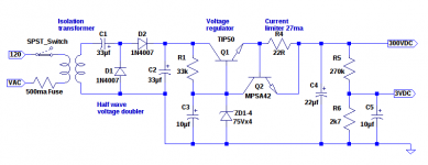
Here are the schematics for what I have so far.
I decided to put a current limiter on the voltage regulator. In the hope that if I slip with the scope probe and accidentally short the power supply, it won't be instant death to the TIP50 pass element.
I haven't tested the short circuit thing yet, but I did hang a 5k load off the power supply.
At 300v, this would be 60mA. The current limiter is set for 27mA.
I measured across the 22R resistor and it is 0.6v, so yes that is 27mA.
If the current was 60mA, I would measure 1.32v across that 22R.
So I guess it's working.
What I don't fully understand is how it manages to hold the voltage at nearly 300v with a 5k load and only pass 27ma, but it does.
Seems to me 27mA through 5k is 135V so I should measure 135V across the load.
I didn't spend too much time on this so maybe I'm missing something.
As long as it doesn't oscillate, I'm good.
I chose 27mA arbitrarily because I had a 22R handy.
As it stands, the preamp draws about 6ma.
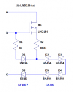
You'll notice that the interstage resistors and tone stack connect to the +3 rail instead of ground. This is because I'm using fixed bias on the LND150 "triodes" and the "grid" needs to be at +3v.
The +3v rail is at ground potential as far as AC signal is concerned.
Since this is an AC ground I need to remember to "star ground" these connections when I rebuild the circuit on another medium besides the solderless breadboard. Of course, the real ground will be star grounded as well.
Attachments
Thank you! That's helpful, and easy to do. I'll stick a BC550C emitter follower ahead of the 2BJTE circuit for testing.Emitter of a SS BJT (2SC2458)
http://www.axiomdrift.com/schematics/BossOD-3.gif?i=1
-Gnobuddy
That is encouraging. That was more or less your primary goal, wasn't it?With the volume knob set around 3, pretty good Fender clean.
Earlier we (well, some of us) were discussing how op-amps are accurate and fast and precise, and sound horrid with electric guitar. Meantime, slow and sloppy and squishy valve stages sound better (again, with electric guitar.)Uh-oh, there's that dreaded "fizz"
<snip>
But headphones are just not the correct tool for this job.
I think headphones are the acoustic equivalent of op-amps: accurate, fast, precise - and they sound horrid with electric guitars.
Meantime, guitar speakers are slow (no tweeter), sloppy (poor Qts and lots of cone breakup), and squishy (poor transient response, stiff surround limiting cone excursion). And hey, they sound better (than headphones) with electric guitars!
I keep coming back to the idea that solid-body electric guitars really are inherently nasty-sounding beasts, and what a good electric guitar amp does is "sandpaper off" a lot of harsh edges and sharp corners from the sound. After that treatment, the guitar sounds good. (Still not as good as any of the classical orchestral instruments, though. I can understand why many people hated electric guitars so much when they first burst onto the music scene.)
Perhaps that means the guitar speaker is a much more agressive low-pass filter than the graphic EQ?Even with the graphic eq bypassed, most of the fizz is gone.
Simplified theory says that you get a 2nd order (12 dB/octave) treble rolloff after the first cone breakup mode, and then an additional 2nd order filter for each additional cone breakup mode as you go up in frequency.
A while ago, I tried roughly fitting straight lines to the published high-frequency response of an Eminence Legend something-or-the-other, and sure enough, there was a region that was reasonably close to 12 dB/octave, and when you went up a little higher in frequency, there was a region that fell at about 24 dB/octave. There must have been an additional cone-breakup mode between those two regions.
My de-nastifying filter only had a 12 dB/octave treble rolloff. It worked well for my amp, which only has clean tones.
I think mjd_tech has just shown that, for overdrive, even steeper and/or more aggressive treble rolloff may be required.
One possibility would be to build a two-channel preamp, and have a more aggressive de-nastifier in the "dirt" channel.
Very cool, and IMO, it's quite unusual for a solid-state circuit to manage both those things.I'm hearing a hint of the Fender "gling" in the clean sounds.
Pretty good "rawk" tone with volume control dimed.
I just had the same experience! The amp I just built for my friend was powered by a 24V switching power supply with a two-wire power cord.I just realized my "ground" is totally floating, it's not connected to earth. I'm using a two prong power cord. It's amazing the hum and noise are not worse than what they are.
I was half expecting to have to go out and buy another power supply, one with a three-wire cord, and a ground wire connection to the DC output. But in the end, hum was very slight, and not bothersome. Whew!
Printer2 was sophisticated enough to engineer that into his breadboard. I'm was only smart enough to steal his idea and implement a cruder version - I bought a big shallow baking tray from the dollar store, and my breadboard will sit inside it, with a ground wire running to the tray!Unlike you sophisticated guys, I have no ground plane under my breadboard either.
There will be about 3/4" (the thickness of the pine plank) between breadboard and ground plane. I hope it still works. It's gotta be better than nothing, though.
You've made me really curious as to how aggressive a de-nastifying filter would be needed to make "rawk music" sound smooth and luverly through them!It's quite interesting how a guitar speaker and air filter out a lot of the fizz and muck.
It really sounded awful in those headphones.
If filtering alone doesn't do it, and we really do need "air", it's always possible to simulate the "air" part with delay and/or reverb. But building that into a de-nastifier is a bit of a headache.
I know there are reverb chips out there ( Spin Semiconductor - Products ) but I don't know if I want to tackle that level of electronic construction complexity today; it will just take away time I would otherwise spend with my wife, or making music, and I'm old enough to know I'll never get that time back.
Something like this is still a possibility (they'll solder the SMD chip for you): Li'l Reverb Kit – Build Your Own Clone . It could be built into a de-nastifier.
I do have a reverb pedal already, but that's staying on my pedalboard. I'm not about to build that one into a de-nastifier!
There you go, you were way ahead of me. Yeah, I'm eager to find that out, too!Next, I need to hook it up to the power amp and bookshelf speakers, as that is the intended use. Still unknown what kind of de-nastifying filter will be needed.
When I measured it, I was shocked to find my de-nastifier had a peak at 2 kHz and rolled off everything above that. My graphic EQ is a crude 7-band one, and I had set the 6.4 kHz slider to minimum - but it was only when I measured the frequency response that I found out that this actually rolled off everything above 2 kHz. (There's a pic of the EQ pedal in post #8, page 1, of this thread.)
So what will have to happen to tame "fizz"? Maybe your filter will have to peak at 1 kHz? Or maybe that will sound too dull, and some delay or reverb ("air") will be a required part of the de-nastifier.
Thanks for the continued reports, and I'm looking forward to the next installment!
-Gnobuddy
YouTube
-Gnobuddy
Mc Laughlin does not impress me that much, but the drummer is fantastic. I think he worked with Jeff Beck & Tal Wilkenfield as well
if you have a look at frequency responses of common guitar speakers you will find them rising up to a peak between 3 and 5khz and then drop very steeply with slopes up to 40dB/oct.
You mentioned spin-semi. I have build several units with their FV-1, using reverberation and chorus. Chorus is quite nice, reverb is not too bad. But it is unlikely for me to find a real satisfactory reverberation emulator since I heard Wolfgang Schwartz demonstrate his Quantec Room Simulator during Ars Electronica 1982.
You mentioned spin-semi. I have build several units with their FV-1, using reverberation and chorus. Chorus is quite nice, reverb is not too bad. But it is unlikely for me to find a real satisfactory reverberation emulator since I heard Wolfgang Schwartz demonstrate his Quantec Room Simulator during Ars Electronica 1982.
Last edited:
You read my mind, this is exactly what I've been doing for the last half-hour!if you have a look at frequency responses of common guitar speakers you will find them rising up to a peak between 3 and 5khz and then drop very steeply with slopes up to 40dB/oct.
(I did the same thing some weeks ago, but apparently I didn't get my slopes right that time. I made some mistakes trying to interpret slopes in dB/octave units. I'm pretty sure I got them right this time, though.)
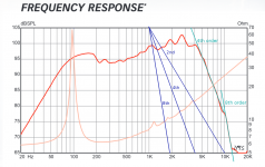
See the attached image - all the text that follows is based on it. The image is the manufacturer's published on-axis frequency response of an Eminence Legend 1028K speaker.
First, for illustration, I drew straight lines (dark blue) representing 2nd, 4th, and 8th order filters, starting at the top of the graph, at 1 kHz. Use these slopes to guide your eyes when looking at the actual loudspeaker frequency response.
From about 4 kHz to 10 kHz, this speaker rolls off treble at the same slope as a 4th order low pass filter. That is to say, 24 dB/octave, or 80 dB/decade.
Above 10 kHz, the rolloff is a close fit to an 8th order low pass filter (48 dB/octave, or 160 dB/decade), until the measurement runs into the noise floor and flattens out.
However, this 8th-order region is more than 25 dB below the peak output at around 3 kHz, so it should have very little audible effect.
So a 4th-order low pass filter would be needed to make a de-nastifying filter that matches the on-axis acoustics of an Eminence Legend 1028k.
(The filter I made for my amp is only 2nd order.)
The remaining question is, what does the frequency response look like from a more typical guitar amp listening location (it's never on-axis)?
I don't know the answer. We can guess the rolloff starts at lower frequency - but how much lower? And does it still start rolling off at 4th order, or does it roll off more gently at first, perhaps only 2nd order, due to the directionality of the speaker, before transitioning into 4th order rolloff further up in frequency?
At this point we have two choices: the more scientific route is to get a measurement microphone and suitable measuring equipment, and measure the frequency response of a few guitar speakers well off-axis, say 30 degrees.
Or we can build a 4th order filter, and see if it de-nastifies solid-state "fizz" as well as an actual guitar speaker does. Less scientific, but quicker, and it may tell us what we need.
-Gnobuddy
P.S. The bass roll off below about 70 Hz is a close fit to a 2nd order high pass filter, as theory predicts for a speaker on an infinite baffle.
Attachments
- Status
- Not open for further replies.
- Home
- Live Sound
- Instruments and Amps
- Tube Emulation & EQ