Thing is with normal sensitivity (not sure what that is as it was meant for a Magnavox tube preamp and was used in a Magnavox console and as such could be anything) I'd have issues given the preamp is passive or can be unity gain when in active mode. Offers no gain whatsoever.
Changing the gain to normal would require a bit of work to get the amp back flat to 20kHz.
Changing the gain to normal would require a bit of work to get the amp back flat to 20kHz.
It is the only solution leading to normal performance.
Or have a preamp instead of a buffer (the Schiit) or a combination so a preamp with moderate gain (and low Zout before the word “tube” comes to mind) and power amplifier with gain adapted to the new preamp with moderate gain. As you could conclude the Schiit is exactly what you don’t need in the current setup. It is not difficult. You decreased input sensitivity of the power amplifier and married it to a non gain preamp.
What is the input sensitivity of the power amplifier like it is now?!
Last edited:
If I wanted normal performance I'd have left the amp stock.
It's about making the amp sound as good as reasonably possible.
It's about making the amp sound as good as reasonably possible.
The Saga seems to be capable and has a low output Z.
''...The pre-amplifier has 75 ohms for its output impedance, while > 5V RMS for its maximum output. For output impedance, it varies, yet has a maximum of 4.8 kOhms....''
''...The pre-amplifier has 75 ohms for its output impedance, while > 5V RMS for its maximum output. For output impedance, it varies, yet has a maximum of 4.8 kOhms....''
But it has no gain while you changed the amplifier so it needs higher input signal levels. Why did you otherwise need extra gain after the Schiit? Please let’s use simple logic. It makes absolutely no sense to sacrifice performance of all parts of the chain if only one of the parts has (partly self inflicted) irregularities. If that device can not work well otherwise it may have tubes nicely glowing but is a bag of hurt regardless.
How did that work out when looking at at it as a sum of things? This was my input, good luck with making it right.
BTW wparks did nail it exactly way before I did I see now.
If I wanted normal performance I'd have left the amp stock.
It's about making the amp sound as good as reasonably possible.
How did that work out when looking at at it as a sum of things? This was my input, good luck with making it right.
BTW wparks did nail it exactly way before I did I see now.
Last edited:

The amplifier had to be changed to eliminate the problem I had of the output rising as the frequency increased with nothing working to fix that other than the way the amp was changed for the driver and phase splitter.
Due to not using a resistor to ground on the input of the amp and the bias supply having 100mV of ripple I had hum. Fixing those eliminated that hum.
All I now have is a slight barely audible rushing sound which is likely coming from the tube buffer.
Otherwise the amp is working great and sounds very good.
Just by redoing the bias supply to where it has only 5mV of ripple and installing the 47k resistor on the input to ground I can unplug the input cable and the amp is pretty much dead silent.
That said it almost sounds like how a tube might do when microphonic so maybe the 12AT7 is slightly microphonic and is somehow picking up the noisy computer fan or some other vibration or noise.
Yeah, when you ask for help in the forum, sometimes the mechanics start tearing apart portions of the system you didn't think needed (or want) to be fixed. Sorry, it's 'what we do'. And once jean-paul gets a hold of it, hang on to your fillings, because you are getting a full exam. Been there done that. I interpret it as passion, which I think we can all understand and respect here.
BTW- I don't usually trust Google AI for much, but:
2V RMS
The standard CD-player output voltage is 2V RMS, with units varying between 1.74V on the low side (the Audio Research DAC1) and a whopping 7.2V on the high side (the Theta DS Pro Basic). Most CD players and processors put out between 2.2V and 3.5V.
As far as Magnavox input sensitivity, I am going to go with what Dave Gillespie had on his two big Maggie rebuilds (on Audiokarma)- The 9300 push pull was full output power at 0.6Vrms, and the 8600 single ended was full power at 0.5Vrms. That feels right, and why I install a 10K input volume pot on all of my Maggies so I can listen to my Denon CD player mano-a-mano, with the volume at about 9-10 o'clock or so on a log pot. Assuming proper output to input impedance matching, that gives the pre-amp with little or (preferably no) gain plenty of ability to provide maximum volume to the power amp even for weaker sources.
I was wondering if you could explain better what you meant by "output rising as the frequency increased", and you indicate several times you had problem getting the amp to work up to 20KHz? Did you ever hear of these problems on the stock amp? I had wondered earlier, what type of characterization did you do to optimize the global feedback network after you changed the input stage gain, and output transformer? Both would change the dynamics of the amplifier, and the amount of, and frequency compensation of global feedback would have to be adjusted to optimize both the global gain and stability.
For both the 9300 and 8600 build, Dave shows images of square waves he took into unloaded, and loaded (and capacitively loaded) output to analyze stability and frequency response. On the 9300 he tuned the global feedback to achieve frequency bandwidth 40-20Khz, very stable with a lot more power than original. On the 8600 he achieved 25hz to 40Khz, also with way more power. The gain of the input stages was not decreased- stability was increased. Both of these builds are excellent reads as to the feedback optimization process if you are interested.
BTW- I don't usually trust Google AI for much, but:
2V RMS
The standard CD-player output voltage is 2V RMS, with units varying between 1.74V on the low side (the Audio Research DAC1) and a whopping 7.2V on the high side (the Theta DS Pro Basic). Most CD players and processors put out between 2.2V and 3.5V.
Quality Lies in the Details Page 2 | Stereophile.com
As far as Magnavox input sensitivity, I am going to go with what Dave Gillespie had on his two big Maggie rebuilds (on Audiokarma)- The 9300 push pull was full output power at 0.6Vrms, and the 8600 single ended was full power at 0.5Vrms. That feels right, and why I install a 10K input volume pot on all of my Maggies so I can listen to my Denon CD player mano-a-mano, with the volume at about 9-10 o'clock or so on a log pot. Assuming proper output to input impedance matching, that gives the pre-amp with little or (preferably no) gain plenty of ability to provide maximum volume to the power amp even for weaker sources.
I was wondering if you could explain better what you meant by "output rising as the frequency increased", and you indicate several times you had problem getting the amp to work up to 20KHz? Did you ever hear of these problems on the stock amp? I had wondered earlier, what type of characterization did you do to optimize the global feedback network after you changed the input stage gain, and output transformer? Both would change the dynamics of the amplifier, and the amount of, and frequency compensation of global feedback would have to be adjusted to optimize both the global gain and stability.
For both the 9300 and 8600 build, Dave shows images of square waves he took into unloaded, and loaded (and capacitively loaded) output to analyze stability and frequency response. On the 9300 he tuned the global feedback to achieve frequency bandwidth 40-20Khz, very stable with a lot more power than original. On the 8600 he achieved 25hz to 40Khz, also with way more power. The gain of the input stages was not decreased- stability was increased. Both of these builds are excellent reads as to the feedback optimization process if you are interested.
Attachments
I should clarify that global feedback only works to reduce gain, and will not increase gain above what the open-loop amplifier can do, but does determine how much of that (hopefully very high open-loop gain) is available in the final, closed loop amplifier. Generally the amplifier inside the feedback loop needs to be very high gain, which I am surprised lowering the input stage gain is a win frequency range wise. Tube amps are known for having pretty stellar frequency range, so something is wonky here if you were having trouble getting to 20Khz. Was that at full power level? (Usually frequency range is measured at rated load, but lower power level, and power bandwidth is measured loaded full power (to the -3dB half-power points) I believe.
Yeah, when you ask for help in the forum, sometimes the mechanics start tearing apart portions of the system you didn't think needed (or want) to be fixed. Sorry, it's 'what we do'.
I don't mind as sometimes that's what's required to get it through my thick skull.
I do know higher end audio equipment can put out more voltage which makes sense as the preamp or amp doesn't need as much gain and is more immune to hum and noise, however regular consumer grade electronics especially older things usually don't put out that much in my experience.
output rising as the frequency increased
What I mean is I fed a sinewave into the amplifier and as I increased the frequency while keeping the input level the same the output across a non-inductive load at the rated output impedance the output would increase some and at one point it would increase then decrease as I got closer to 20kHz.
Did you ever hear of these problems on the stock amp?
Yes I specifically had that problem with the stock amp, however I did not have the stock output transformer, but used an Edcor of the same primary impedance.
I had wondered earlier, what type of characterization did you do to optimize the global feedback network after you changed the input stage gain, and output transformer? Both would change the dynamics of the amplifier, and the amount of, and frequency compensation of global feedback would have to be adjusted to optimize both the global gain and stability.
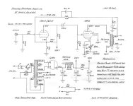
I used the trimmer cap which is in series with a 150pF cap as shown on the schematic.
Not sure when these measurements were taken, but it shows the problem I had. I adjusted the trimmer cap until I had the least rise in frequency when I did the same test.
Both of these builds are excellent reads as to the feedback optimization process if you are interested.
I'll definitely take a look at those builds.
which I am surprised lowering the input stage gain is a win frequency range wise.
At least I think the gain was lowered, however I am not totally sure. Been so long that I cannot remember.
Tube amps are known for having pretty stellar frequency range, so something is wonky here if you were having trouble getting to 20Khz.
Not sure what was wrong with the stock circuit. Maybe it just didn't like the Edcor transformer? That's the only thing I can think of.
Was that at full power level?
I forget what power level it was at. I do know the amp responds differently as at a lower output the response doesn't vary much at all when doing the test I showed in the photo, however at a higher output there was more variance.
Too much info to post here, but these two links show more of the history of the amp and the problem. The posts are in a Facebook group called Vacuum Tube Amplifier
https://www.facebook.com/share/p/12Evx7ksYE1/
https://www.facebook.com/share/p/1AFJgRRyyq/
Also this post in another forum has more history on the amp and the problem.
https://audiokarma.org/forums/index.php?threads/magnavox-amp-142-rebuild.998590/
I think you're in a good place at this point. The more I stare at that schematic the more it gives me a headache. I'll admit, I'm in over my head when it comes to the meat of complex amplifier design, especially odd ducks. I did the same thing- followed recipes that were ironed out for me by smarter people, learned a bunch along the way, and fortunately it worked great even if I did not understand all of the details. Best I can do since I don't have the years to invest in the specific education to work at that level. The behaviors you indicate may be 'normal', I just don't know.
followed recipes that were ironed out for me by smarter people, learned a bunch along the way, and fortunately it worked great even if I did not understand all of the details.
Same.
The behaviors you indicate may be 'normal', I just don't know.
I'm not sure either.
Only thing I can figure is either its the mismatched output tubes (two different brands) or the circuit just doesn't like the output transformer and needs the compensation or it's how the circuit is laid out.
I'd love to either purchase or borrow a bone stock AMP-142 in fully working condition so that I can perform tests on it just to see if it exhibits the same problem.
Out of the several tube amps I've built and rebuilt I've never seen the particular issue this amp had.
Even with what I know about tube amps I cannot explain why it had that issue.
Even with what I know about tube amps I cannot explain why it had that issue.
Now that I have had a chance to sit down and re-read much of what Dave posted in the 9300 series re-design, I am understanding that rising output with frequency is a very common issue, caused by approaching the resonant frequency of the output transformer. In high quality transformers this is normally compensated out with a small capacitor across the feedback resistor because the OPT resonance is high enough the negative effects of the compensation happen above audible frequencies. In the Magnavox amps, the stock transformers had a relatively low resonant frequency near the audible range with effects down as far as mid-band so rising output was quite noticeable, so Magnavox typically used hobbled phase inverters with HF roll off to somewhat compensate. Dave describes this very well in various posts in that redesign, with post #67 on page 4 being perhaps the most germane. I don't know what the resonant frequency of your Edcore is- Was this exact transformer specified in the reworked design you used from Facebook? I think maybe by redesigning the phase splitter to perform more flatly that this exposed the same issue in the Edcore.
The floating pharaphase inverter that Dave employed is really quite simple, and beautiful in it's performance. He details that in post #73. With perhaps some manageable changes perhaps you could give it a go. Later in the posts of this very long thread, he upgrades the output transformers and talks about how he adjusts the negative feedback to accommodate the new transformers. I must admit, after looking at that big spacious chassis you have, I would have been motivated to add a second matching transformer and modify it into a stereo 6V6 push-pull.
The floating pharaphase inverter that Dave employed is really quite simple, and beautiful in it's performance. He details that in post #73. With perhaps some manageable changes perhaps you could give it a go. Later in the posts of this very long thread, he upgrades the output transformers and talks about how he adjusts the negative feedback to accommodate the new transformers. I must admit, after looking at that big spacious chassis you have, I would have been motivated to add a second matching transformer and modify it into a stereo 6V6 push-pull.
You're certainly using a novel FB system. Never seen FB going to the cathode and grid on the same tube.
I could have done stereo, however I needed a mono amplifier.
I basically use a floating paraphase already, however I will see how Dave's implementation is different from the one I used.
Thanks for the explanation. Now I understand why I had that problem and never saw it in any other amplifier.
I wonder if the tuner chassis had some compensation built in as well? That said typical cone tweeters usually don't go much above 13kHz so any rise in output above 13kHz wouldn't have been noticed or maybe would have extended the frequency response slightly.
I never have either, however I've never dealt with a floating paraphase inverter before as I've always used other designs for my own builds.
I basically use a floating paraphase already, however I will see how Dave's implementation is different from the one I used.
I am understanding that rising output with frequency is a very common issue, caused by approaching the resonant frequency of the output transformer. In high quality transformers this is normally compensated out with a small capacitor across the feedback resistor because the OPT resonance is high enough the negative effects of the compensation happen above audible frequencies. In the Magnavox amps, the stock transformers had a relatively low resonant frequency near the audible range with effects down as far as mid-band so rising output was quite noticeable
Thanks for the explanation. Now I understand why I had that problem and never saw it in any other amplifier.
so Magnavox typically used hobbled phase inverters with HF roll off to somewhat compensate.
I wonder if the tuner chassis had some compensation built in as well? That said typical cone tweeters usually don't go much above 13kHz so any rise in output above 13kHz wouldn't have been noticed or maybe would have extended the frequency response slightly.
You're certainly using a novel FB system. Never seen FB going to the cathode and grid on the same tube.
I never have either, however I've never dealt with a floating paraphase inverter before as I've always used other designs for my own builds.
Not quite sure what it is given how the .47uF cap connects as I've not seen a phase inverter quite like that, however it does work fine and provides balanced outputs.
Far as feeding a squarewave into the amp, what frequency should I use?
Far as feeding a squarewave into the amp, what frequency should I use?
Last edited:
10Khz seems to be the common freq. to use when tweaking a phase cap. Mid band, I guess. But it's interesting to sweep it to see how well the OPT & FB handles the low freqs. Expect sloping as you tune it lower.
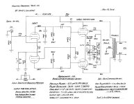
The heater should be raised above cathode.
Made positive relative to cathode
My 6922 heaters are at +40 volts.
Your schematic has the 6.3v heater winding at negative voltage.
Made positive relative to cathode
My 6922 heaters are at +40 volts.
Your schematic has the 6.3v heater winding at negative voltage.
- Home
- Amplifiers
- Tubes / Valves
- Tube audio buffer