
Provides the most big stage and detailed sound. Each tube anode rail voltage is provided by 2 x 100uf ķ75 film caps for pulse applications. Attack in fast sound is wonderful
Which OPTs are you using? I agree that the PS with nice caps (new production HV Polypropylene) can be made for less than 1000, what becomes expensive are the OPTs...For $350,000 do you even get polypropylene filter capacitors in the high Voltage power supplies? Using the best parts money can buy you pay under $2000 for parts to build an amplifier at least as good as the WAVAC. I don't have the know how to perform the psychological manipulation it takes to get anyone to pay me $348,000 for a week or two of the labor it takes to build that kind of an amplifier and it would not surprise me if most people could build one faster than I can, but getting so conspicuously overpaid would not be honest or fair to any customer so I would not do it even if I could.
The good quality OTP transforners for 833 tubes is a difficult technical task. Monolith Magnetics is a good choice. But 2kV power supply is another challenge. Anode transformer is a challenge, in northern countries. Nobody would like to be killed by a unit, even good sounding. In real life, 1kV plate voltage has been prooven to be enought. Good anode voltage plate capacitors is a must.
I built a GM70 with about 900V and did that with a lot of respect 🙂 Nice is that the GM70 has no exposed caps!
I asked mostly because @drbarney1 mentioned "best part money can buy you pay under $2000", that would be hard. But well, he does not specifically state parts for a >100W SE amplifier, so maybe that is the catch 🙂
I asked mostly because @drbarney1 mentioned "best part money can buy you pay under $2000", that would be hard. But well, he does not specifically state parts for a >100W SE amplifier, so maybe that is the catch 🙂
With GM70 output stage, I did some steps up soundwise, by replacing graphite plate GM70, then by copper plate GM70, then by "metal plate" GM70. But in all cases capacitor multypliers are used. With GKE100, now, there is no capacitor multypliers, no electrolytis, substantial chokes are used at GKE-100 output stage. This way, with vacuum tubes rectifiers, sound is definitely better. My best greetings to LAMM ML3 rare technical solution.
Hum less, HV plate transformer sometimes is even bigger headache than OPT.Anode transformer is a challenge
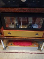
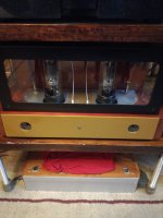
How much is GKE100's anode current settings?Contains 8pcs vintage VO-188 tube rectifiers for providing 950V plate voltage. Contains no any electrolytic capacitor no any semiconductor
Rail voltage 940V, plate voltage 930V, plate current 100mA, voltage readings on heater (cathode) pins 95,5/84,7, power dissipated on anode+second grid is 84W
Thank you vladimirk!There are no small differences between this working point and characteristic curve.
Hi, 🙂 before few years, i made some spice model against measured anode chrs in triode mode for GKE-100.
Ri of the tube is about 2Kohm in most of the region of the "middle space" where the working point has to be choosen.
So with some RLoad Req if the generator for the OT is about 1500ohms.
.
GKE-100 spice model with capacitance values in the txt:
.
GKE-100 = GE1
GE1 capacitances:
CCG=15.5pF
CGP=0.055pF
CCP=10pF
** GKE_100 ** Composite DHT with Advanced Grid Current ************
* Created on 01/24/2021 15:48 using paint_kit.jar 3.1
* www.dmitrynizh.com/tubeparams_image.htm
* Plate Curves image file: /Users/zoran/Desktop/Model_Paint_Tools/Graph/GKE-100.jpg
* Data source link:
*----------------------------------------------------------------------------------
.SUBCKT DHT_GKE_100_A2 1 2 3 4 ; P G K1 K2
+ PARAMS: CCG=15.5P CGP=0.055P CCP=10P RFIL=10
+ MU=5.1 KG1=5665 KP=103.5 KVB=845 VCT=0.2 EX=1.413
+ VGOFF=-0.6 IGA=0.001 IGB=0.5 IGC=8 IGEX=2.03
* Vp_MAX=1375 Ip_MAX=300 Vg_step=20 Vg_start=80 Vg_count=118
* Rp=5000 Vg_ac=100 P_max=80 Vg_qui=-100 Vp_qui=780
* X_MIN=68 Y_MIN=159 X_SIZE=968 Y_SIZE=523 FSZ_X=1853 FSZ_Y=911 XYGrid=true
* showLoadLine=y showIp=y isDHT=y isPP=n isAsymPP=n showDissipLimit=y
* showIg1=y gridLevel2=y isInputSnapped=n
* XYProjections=y harmonicPlot=y dissipPlot=y
*----------------------------------------------------------------------------------
RFIL_LEFT 3 31 {RFIL/4}
RFIL_RIGHT 4 41 {RFIL/4}
RFIL_MIDDLE1 31 34 {RFIL/4}
RFIL_MIDDLE2 34 41 {RFIL/4}
E11 32 0 VALUE={V(1,31)/KP*LOG(1+EXP(KP*(1/MU+V(2,31)/SQRT(KVB+V(1,31)*V(1,31)))))}
E12 42 0 VALUE={V(1,41)/KP*LOG(1+EXP(KP*(1/MU+V(2,41)/SQRT(KVB+V(1,41)*V(1,41)))))}
RE11 34 0 1G
G11 1 31 VALUE={(PWR(V(32),EX)+PWRS(V(32),EX))/(2*KG1)}
G12 1 41 VALUE={(PWR(V(42),EX)+PWRS(V(42),EX))/(2*KG1)}
RCP1 1 34 1G
C1 2 34 {CCG} ; CATHODE-GRID
C2 2 1 {CGP} ; GRID=PLATE
C3 1 34 {CCP} ; CATHODE-PLATE
RE2 2 0 1G
EGC1 81 0 VALUE={V(2,31)-VGOFF} ; POSITIVE GRID THRESHOLD
GG1 2 31 VALUE={0.5*(IGA+IGB/(IGC+V(1,31)))(MU/KG1)(PWR(V(81),IGEX)+PWRS(V(81),IGEX))}
EGC2 82 0 VALUE={V(2,41)-VGOFF} ; POSITIVE GRID THRESHOLD
GG2 2 41 VALUE={0.5*(IGA+IGB/(IGC+V(1,41)))(MU/KG1)(PWR(V(82),IGEX)+PWRS(V(82),IGEX))}
.ENDS
*$
Attachments
Last edited:
Why did you decide that Rp ohm = 5000 Ohms
in my case, with 4 ohm speakers, output transformer windings ratio is 52 : 1
That means at least Rp = 10 000 Ohms, and Ri in my case is 1800 Ohms
In any case, mile stones in this design, only vacuum rectifiers, no electrolytics, no semiconductors, film caps designed for pulse current applications.
Who would repeat this design approach, please be welcome to comment his sound impressions in this thread.
Hi i use max Pmax=80W. And some model with partial FB.Why did you decide that Rp ohm = 5000 Ohms
in my case, with 4 ohm speakers, output transformer windings ratio is 52 : 1
That means at least Rp = 10 000 Ohms, and Ri in my case is 1800 Ohms
In any case, mile stones in this design, only vacuum rectifiers, no electrolytics, no semiconductors, film caps designed for pulse current applications.
Who would repeat this design approach, please be welcome to comment his sound impressions in this thread.
.
I done more accurate spice model in DHT mode with capacitances.
And 9K to 10K as Rload for the GKE-100 is more proper value in the terms of decreasing distortion.
.
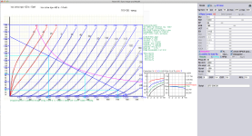
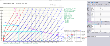
The tube is very linear in triode mode. With these settings of Ug=-130V, Ia=97mA, Va=940V, Pa=90W, Rload=10Kohm
distortion are very very low.
1W=68Vp-p input=0.22%THD
5W=148Vp-p input=0.51%THD
10W=210Vp-p input=0.79%THD
max before A2 class:
15.32W=260Vp-p input=1.06%THD
For my opinion these estimated results based on static considerations are very, very good. And 15.3W is more than enough for domestic use.
(Of-course that the tube with driver and input tube circuit will add some more distortion, because of the high input swing
of 260Vp-p at G1 of power tube... )
.
But It is not clear what is max P. max Panode=80W + G2=?
(These settings are for max. 90W)
.
No the Ri is in wide region of different working points, 2K (1980ohms)
Please see in the picture calculated value.
For 10K static load line, Ri(Imax=155mA)=1720ohm, Ri(Io=97mA)=1982ohm, Ri(Imin=43mA)=2780ohm
(There is the big difference of Ri in extreme points. But it is not unusual for tubes... 🙁 )
.
For 5W output power (very loud!!!) difference of value of Ri is much smaller:
For 10K static load line, Ri(Imax=129.5mA)=1820ohm, Ri(Io=97mA)=1982ohm, Ri(Imin=65mA)=2280ohm
.
So the Rgen is parallel value of Rload (10K in example picture) and Ri in Io center point, Req=1655ohms
This Req=1655 ohms is the main factor in OT primary inductance needed for very good LF response and minimum phase shift.
And deserves more [Hy] in Lp primary...
I will simulate latter for minimal -db loss in 20Hz and minimal +deg phase shift.
(It is about the transfer in LF domain, most of the SE designs suffer a lot...)
.
The capacitances are low, so should apply some measures for eventual oscillations?
Amplification factor is also low, (low dynamic capacitances) BUT need of 260Vp-p input signal for max power.
If the 2Vrms=5.66Vp-p is at the input tube of the amplifier then total amplification before power tube should be 260Vp-p/5.66Vp-p=46X cca.
Maybe it is achievable with just one stage with 46x total gain in circuit to drive power tube?
So input tube has to be with mju about 55-60X, (in circuit -A is lower and will drop to 45X), low internal resistance, meduim S
and higher Anode voltage with settings, to avoid huge voltage drop (huge dissipation of heat at R) from Vb of power tube.
.
** Composite DHT ***************************************
- Created on 10/27/2023 22:58 using paint_kit.jar 3.1
- www.dmitrynizh.com/tubeparams_image.htm
- Plate Curves image file: /Users/zoran/Desktop/Model_Paint_Tools/Graph/
- Data source link:
.SUBCKT GKE-100_DHT 1 2 3 4 ; P G K1 K2
- PARAMS: CCG=16.2P CGP=0.76P CCP=10.7P RFIL=5.5
- MU=5.15 KG1=5550 KP=110.08 KVB=780 VCT=0 EX=1.412 RGI=2000
- Vp_MAX=1500 Ip_MAX=330 Vg_step=20 Vg_start=60 Vg_count=18
- Rp=10000 Vg_ac=130 P_max=90 Vg_qui=-130 Vp_qui=940
- X_MIN=54 Y_MIN=111 X_SIZE=1053 Y_SIZE=579 FSZ_X=1902 FSZ_Y=791 XYGrid=true
- showLoadLine=y showIp=y isDHT=y isPP=n isAsymPP=n showDissipLimit=y
- showIg1=n gridLevel2=n isInputSnapped=n
- XYProjections=y harmonicPlot=y dissipPlot=y
RFIL_LEFT 3 31 {RFIL/4}
RFIL_RIGHT 4 41 {RFIL/4}
RFIL_MIDDLE1 31 34 {RFIL/4}
RFIL_MIDDLE2 34 41 {RFIL/4}
E11 32 0 VALUE={V(1,31)/KP*LOG(1+EXP(KP*(1/MU+V(2,31)/SQRT(KVB+V(1,31)*V(1,31)))))}
E12 42 0 VALUE={V(1,41)/KP*LOG(1+EXP(KP*(1/MU+V(2,41)/SQRT(KVB+V(1,41)*V(1,41)))))}
RE11 32 0 1G
RE12 42 0 1G
G11 1 31 VALUE={(PWR(V(32),EX)+PWRS(V(32),EX))/(2*KG1)}
G12 1 41 VALUE={(PWR(V(42),EX)+PWRS(V(42),EX))/(2*KG1)}
RCP1 1 34 1G
C1 2 34 {CCG} ; CATHODE-GRID
C2 2 1 {CGP} ; GRID=PLATE
C3 1 34 {CCP} ; CATHODE-PLATE
D3 5 3 DX ; FOR GRID CURRENT
D4 6 4 DX ; FOR GRID CURRENT
RG1 2 5 {2*RGI} ; FOR GRID CURRENT
RG2 2 6 {2*RGI} ; FOR GRID CURRENT
.MODEL DX D(IS=1N RS=1 CJO=10PF TT=1N)
.ENDS GKE-100_DHT
*$
Attachments
Last edited:
Zoran, great info, thanks for your efforts. I plan to make corresponding pre amplifier for operating this output stage in a2 class . Preliminary measurements show that 40W output power is quite possible.
What is max Panode and max Pg2 for GKE-100?
is the Pa+Pg2=100V max?
.
I took the capacitances from GE1 tube, because i could not find any for GK-100
and add 0.7pF to 1pF for socket-pin capacitance...
CCG=15.5pF
CGP=0.055pF
CCP=10pF
But these for tetrode, for triode mode are different values.
Probably CGP is significantly higher up to 15pF of CCG?
That is what has to be changed in spice model datas.
.
In any case that will be dynamic capacitance of around 80pF.
Cdyn=CCG + abs(-A + 1) x CGP
-A = is gain in circuit. (Negative sign is for phase shift of -180deg in SE anode connection...)
mju=5.15 so A is always less value than mju.
From picture -A is 1107Vp-p anode voltage result with 260Vp-p input
so -A=1107Vp-p / 260Vp-p
-A=4.26
for 10Kohm load line
Last edited:
- Home
- Amplifiers
- Tubes / Valves
- Tube amplifiers with PMC EB1i speakers