GKE-100 looks great as output tube candidate. This tube is not popular and still available for peanuts. I had few of these also.
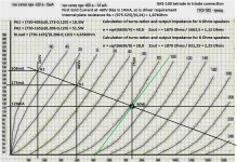
In triode connection, this tetrode tube is quite similar to GM-70 (internal plate resistance, output transformer and output power). Howerver, nobody still used it, maybe because of absence of measurements in triode connection. I think the enclosed picture with calculations is shown here for the first time.
Attachments
GKE-100 is not alone unclaimed tube perfect for DIY audio.
I never seen home amplifier based on my present output tubes also 🙂
I never seen home amplifier based on my present output tubes also 🙂
In triode connection, this tetrode tube is quite similar to GM-70 (internal plate resistance, output transformer and output power). Howerver, nobody still used it, maybe because of absence of measurements in triode connection. I think the enclosed picture with calculations is shown here for the first time.
Oh, the output powers above are wrong, in the picture attached to #61, I have not divided by two. Correct data are here. So, at 750V anode voltage one does not have output power compared to GM70. One needs to consider higher anode voltages.
Attachments

Last edited:
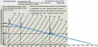
Oh, at 1000V 95mA work point, and 10k load applied to anode, calculations for GKE-100 in triode connection are much better. One obtaines real 20W output power in A1 mode with 0,75 Ohms output impedance. However, requirements to driver stage are: 280V p-p in A1 mode, and 400V p-p in A2 mode.
Attachments
Last edited:
GU46
VladimirK, with 500 to 700Ohm we should use an output transformer of about 2000 to 2500 Ohm and so it might be difficult to get to 70W with 700V supply (I suspect this is the highest shield voltage). Or would you consider having higher voltages for the GU46 in triode mode?
I'm building with GU46 but in pentode so I can use over 1500V(and use 10k transformer). Can you comment on this and helping me to get the best of the GU46?
Thanks
Also, the GU-46 tube is good for the output units of powerful single-ended amplifiers.
The maximum power dissipated at the anode is 500 W, in a triode connection the voltage gain is about 5, the internal plate resistance is 500-700 Ohm, depending on the operating point.
I enclose the results of preliminary (incomplete) measurements of the GU-46 in the triode connection (because of limited power of my test anode transformer). With SE output stage, one can easily get an output power of 70-100 W in A1. Big output transformers will be more simple in design, than for GU-48.
VladimirK, with 500 to 700Ohm we should use an output transformer of about 2000 to 2500 Ohm and so it might be difficult to get to 70W with 700V supply (I suspect this is the highest shield voltage). Or would you consider having higher voltages for the GU46 in triode mode?
I'm building with GU46 but in pentode so I can use over 1500V(and use 10k transformer). Can you comment on this and helping me to get the best of the GU46?
Thanks
I am absolutely sure, we can use higher voltages on the screen grid in triode mode, than it is limited in datasheets for the penthode or tetrode modes.
How high the voltage on the screen grid of a triode-connected pentode can be, even tube manufacturers cannot clearly answer this question. From the experience of many practical applications, we came to the conclusion that the maximum voltage on the screen grid for pentode (tetrode) connection, indicated in datasheets, does not apply to triode mode of the tube. In a triode connection, the screen grid is connected to the anode, usually through a resistor of about 100 ohms, and one can practically forget about some voltage limitations on the screen grid of the "pseudotriode" in typical conditions of use of the "pseudotriode".
As for a possible explanation of this situation, the main role is obviously played by the maximum allowable power dissipated on the screen grid. In a pentode / tetrode connection, the screen grid adsorbs a significantly higher electron flux than in a triode connection. Especially when the anode voltage becomes less than the screen-grid voltage in operating mode, the screen-grid current rises sharply.
In the case of "pseudotriode", we create conditions for reducing the power dissipated on the screen grid. For output pentodes and tetrodes, the control and screen grid usually have the same winding step, the turns of the screen grid are "in the shadow" of the turns of the control grid, and therefore, with a greater and equal anode potential, electrons fly beside the screen grid, being deposited on it to a small extent. This causes the small screen-grid current in the triode mode.
GU46
Yes, you're right about screen voltage and screen current, but in this case (GU46) how much is too much current in the screen?
I can rise the voltage slowly and monitor the current, but can you give me an idea of how much current can it take? I would not like to toast a tube, as I only have two pairs.
Thanks
Maximum screen grid dissipation is 45W. I think the only way you could be sure at testing the tube, connect screed grid to anode by 100 Ohms 3-5W resistor, increase anode voltage and measure voltage drop on the 100 Ohms resistor. Calculate power dissipated on the screen grid. At what anode voltage, the screen grid dissipated power will become close to 40W ? I think, nobody in the world has such information.
you're absolutely right, I had the GU46 working at 1500V plate and shield and with no issues. In fact it works great with a 5k transformer.
Just need more than 220V bias. if you let plate current go over 300mA, the shield current will runnaway.
will make it 1300V and 240mA in triode.
Thanks for your suggestion, it was an eye oppener
Just need more than 220V bias. if you let plate current go over 300mA, the shield current will runnaway.
will make it 1300V and 240mA in triode.
Thanks for your suggestion, it was an eye oppener
Palmas, thanks a lot, this is a great info for those who would like to power up GU46 tubes.you're absolutely right, I had the GU46 working at 1500V plate and shield and with no issues. In fact it works great with a 5k transformer.
Just need more than 220V bias. if you let plate current go over 300mA, the shield current will runnaway.
will make it 1300V and 240mA in triode.
Thanks for your suggestion, it was an eye oppener
If I remember correctly, only one GU46 project was reported on DIYAUDIO up to now.
Me and other people would be interested to see your further steps in your GU46 project.
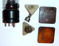
Is the second grid (G2) dissipation (16W) of GKE100 measured data? This parameter is not provided in the datasheet.Among old metal anode tetrodes, that were manufactured in Tashkent in years 1950s, I would mention GKE-100 tube. It is still more affordable than metal anode GM-70. Its maximum plate dissipation is 80W, plus 16W dissipated by the second grid if triode connected, so we come to near 100W dissipation power. Triode curves have been measured by one colleage from Ukraine.
I also heated them up, and was surprised by their stable behaviour. After 70 years of storage, anode current came to stable point after few seconds of operation.
Oh, you are right, I also doubt now about possibility of 16W on G2. I saw this value in some forum discussion, but it indeed is not grounded in datasheets. One should be careful with G2 power. But, there are curves for GKE-100 in triode connection, from them one could estimate power on G2 during such measurements.
A person who did triode connection measurements dissipated much bigger power on anode+G2 than 80W indicated in datasheet. But for long term tube stability 80W at anode should not be violated. For short time power dissipation on G2 can approach 16-20W, but for long term - who knows, special study is needed.
Attachments
Thank you for your reply and information!A person who did triode connection measurements dissipated much bigger power on anode+G2 than 80W indicated in datasheet. But for long term tube stability 80W at anode should not be violated. For short time power dissipation on G2 can approach 16-20W, but for long term - who knows, special study is needed.
Here are some measurements and comments about 833A and GU-48 tubes
http://audio-db.info/AudioDB/BazaPraktiki/Usilenie/Lampy/Alfavit/GU/GU48
.


http://audio-db.info/AudioDB/BazaPraktiki/Usilenie/Lampy/Alfavit/GU/GU48
.

- Home
- Amplifiers
- Tubes / Valves
- Tube amplifiers with PMC EB1i speakers