That 6BS7 topic is definitely worthy of more digging. There is an application doc on it too. First time i have seen microphony spectrum plot in a specific valve`s datasheet, as well as grid current levels and other population statistics.
one rule of thumb in my toolbag, all elements of the tube must connect to something and never left hanging...
have seen this play out in a chinese tube amp wherein the one half of the dual triode was left hanging, after sometime, youse the amp with tubes lit and no sound, simply replacing the tube brought back the sound, but i wonder for how long?
so in that case, i paralleled the unused triode to the corresponding element of the triode used, i.e. pin 1 to pin 6, pin 2 to pin7 and then pin3 to pin8....end of problem...
... how does the circuit 'know' that there is a zero crossing?
....
before that, the capacitor is not charged, so at the top of that cap, at Vraw, you see a double-rectified mains sine wave, positive half-waves. And that goes to zero twice per mains period, easy to detect.
This won't work with a choke input filter, will it?
Member
Joined 2009
Paid Member
Did some more searching about the cathode stripping effect and found the attached. Sounds plausible.
The one thing that struck me in this article is the idea that pieces getting ripped off the cathode would be caught in the sieve of the grid. I have a sieve in my kitchen and it’s made of a tight mesh and I could imagine it catching stuff thrown into it. But when I go look at the grid of an average tube I don’t find such a tight mesh, it’s hard to imagine the grid intercepting very much at all ??
Last edited:
Member
Joined 2009
Paid Member
…softstart is what saves components.
Why does the softstart save components? As far as I can see, the ‘input signal’ of mains ac is at 50Hz / 60Hz and after rectification the waveform is 100Hz / 120Hz which ain’t too impressive. The audio signals run up to 10’s kHz and many components will be subjected to much higher slew rates from the audio signal than they’ll ever ‘see’ from the power supply coming on. I can’t see where the issue is - Have I taken your comment too far out of context by mistake ?
Last edited:
I think the comparison is flawed because the power levels and transient currents in a power supply are in a different order than in the amplifier circuit.
Jan
Jan
My work focuses on solid state amps, not valve amps. In solid state amps with semiconductor rectifiers and large (>500 VA) power transformers, I think of soft start as a protection mechanism whose main purpose is to limit the "inrush current" at switch-on. Lowering the inrush current reduces stress upon the mains fuse, the power on/off switch, the transformer (both primary and secondary), the rectifiers, and the bulk filtering capacitors. Most importantly it lets me select a mains fuse to handle the expected worst case operating current instead of the worst case inrush current. I consider that an improvement in safety.
A very good observation. Applicable on larger tube amps too.My work focuses on solid state amps, not valve amps. In solid state amps with semiconductor rectifiers and large (>500 VA) power transformers, I think of soft start as a protection mechanism whose main purpose is to limit the "inrush current" at switch-on. Lowering the inrush current reduces stress upon the mains fuse, the power on/off switch, the transformer (both primary and secondary), the rectifiers, and the bulk filtering capacitors. Most importantly it lets me select a mains fuse to handle the expected worst case operating current instead of the worst case inrush current. I consider that an improvement in safety.
A simple form is a resistor in the primary that shorts by a relay after a few seconds.
I just want to remind you guys that inrush current issues are a completely different issue than the subject of this thread. Maybe not to hijack it.
Jan
Jan
an NTC in series with the power traffo primary is just about all that is needed for tube power amps...…
my observations using a power monitor at the primary, at the flick of the switch there is a surge of current even as the filaments are still cold, then power goes down, and as the filaments warmed up the power went up and settled to a fixed value...
in all, i never saw that the mains fuse was in danger of busting as the fuse rating was way above the turn on currents that i saw...
with SS amps, there is no such, up down and up again scenario, after the initial surge died down, then it is idle power all the way...
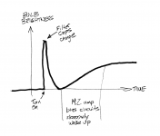
Tony, here's how the solid-state amp called "First Watt M2" behaves, when connected to a Dim Bulb Tester. This amp is class-A so its idle power is quite high, but the optoisolater-based bias control circuit has a very very long timeconstant (> 20 seconds).
At switch-on, there is a large inrush current as the power supply filtering capacitors are charged, and the transformer flux transitions from (zero) to (sinusoidal). Then the bias controller sloooooowly ramps up the current in the output stages and eventually, more than 20 seconds later, the final class-A idle power is reached.
_
Attachments
What is missing in this story is the xformer magnetizing current. If you switch on the transformer on the same waveform position as it was switched off, the magnetizing current is small.
If you switch the xformer on 180deg from the point where it was switched off, it presents basically a short to the mains.
This is all without the effect of any secondary load.
See attached example measurement from my Sequencer project. Inrush magnetizing current with no load is >40A peak on 230VAC mains. (The red curve is just some measurement points to facilitate understanding what's going on).
The sequencer has a small controller that makes sure that the switch off and switch on points were always the same to minimize magnetizing inrush.
Jan
Attachments
A 10 Ohm NTC works perfect to limit that. This is the simple standard method as used with toroids above 500 VA to 1 kVA in 230V mains voltage areas. A 1 part solution.
In telecom 1 kVA toroids were/are used in the field for decades in this way and both toroids and NTCs survive almost anything that happens except lightning strikes. Sidenote: their modern replacements don't last 10 years (SMPS).
In telecom 1 kVA toroids were/are used in the field for decades in this way and both toroids and NTCs survive almost anything that happens except lightning strikes. Sidenote: their modern replacements don't last 10 years (SMPS).
Last edited:
I use a SSR with zero crossing as mains switch. Cheap reliable and surgefree.What is missing in this story is the xformer magnetizing current. If you switch on the transformer on the same waveform position as it was switched off, the magnetizing current is small.
If you switch the xformer on 180deg from the point where it was switched off, it presents basically a short to the mains.
This is all without the effect of any secondary load.
See attached example measurement from my Sequencer project. Inrush magnetizing current with no load is >40A peak on 230VAC mains. (The red curve is just some measurement points to facilitate understanding what's going on).
The sequencer has a small controller that makes sure that the switch off and switch on points were always the same to minimize magnetizing inrush.
Jan
No that is every time power on surge (! when using zero crossing SSR’s !). Worse than a simple power switch.
Hint: it is not a resistor that is being powered. You are definitely not alone in this thinking but unfortunately it is the opposite of what is really happening 🙂 It is also worst scenario for the SSR and the transformer and it may cause EMI/RF ....
Don't repeat this error, folks! Just know your stuff regarding transformers and you'll be able to easily explain what is happening.
Last edited:
Then it might be a nice idea to have the sequencer switch the mains at a voltage peak, both switch-on and switch-off.
Yes, then the magnetizing current is minimum. Of course, the secondary load current inrush charging the caps is maximum then :-(
But if you have a controller in the system anyway, you can apply some intelligence ;-)
Jan
But if you have a controller in the system anyway, you can apply some intelligence ;-)
Jan
- Home
- Amplifiers
- Tubes / Valves
- Tube amp high-voltage delay