Several questions about the zero-crossing switching after the delay has ended: how does the circuit 'know' that there is a zero crossing?
The connection Vraw (J3) connects to the top of the capacitor after the rectifiers, where - after switch-on - the high voltage will appear.
But, and this is not obvious, before that, the capacitor is not charged, so at the top of that cap, at Vraw, you see a double-rectified mains sine wave, positive half-waves. And that goes to zero twice per mains period, easy to detect.
Jan
Attachments
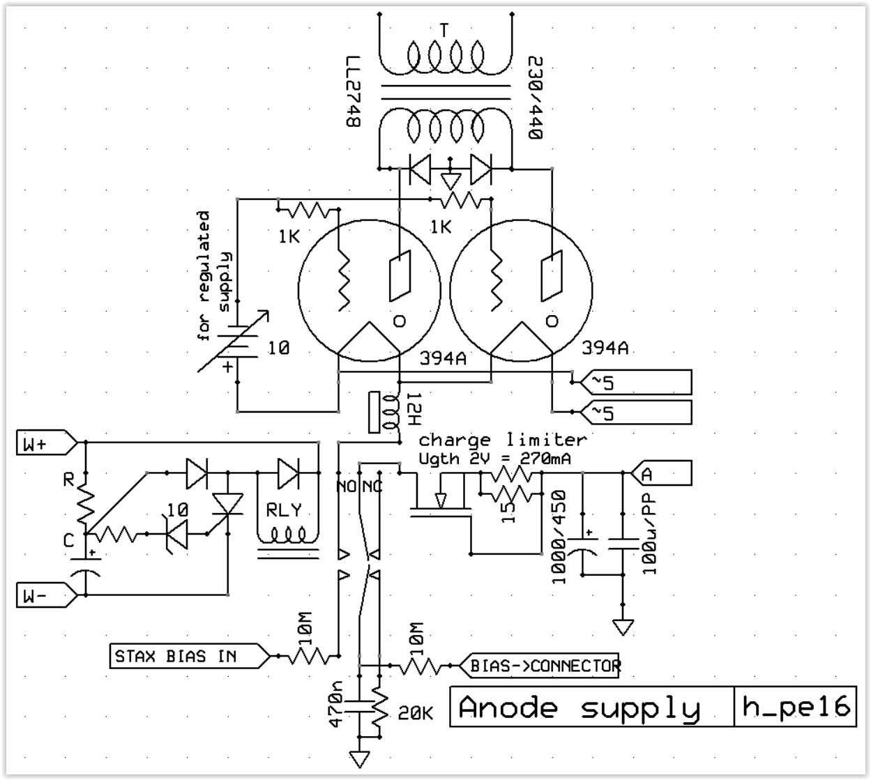
it looks oldschool, but can´t beat a reliable thyristor 🙂
secondly, charge limiter is kind to components; very important when you are feeding 1000µf 🙂 no relay welding, no kaboom.
secondly, charge limiter is kind to components; very important when you are feeding 1000µf 🙂 no relay welding, no kaboom.
I'd say the relay shorts out the charge limiter once the cap is full, but this does not do so...
Physics does not support a delayed switch on. The potential between plate and cathode would need to be several thousand volts to rip electrons from the cathode and also consider the electrolytics. THere is ample literature on the subject if one goes hunting.
I'm just installing an ebay cheapy delay relay (as per post #14) in a valve diode heater circuit. Direct heated diodes like 5U4 are similar to ss diodes in that B+ comes up to a max within a few seconds. Even an indirectly heated diode like GZ34 can bring B+ up a second or two before output stage valves can avoid a B+ overshoot.
Applied to a diode heater, the relay contact really needs to be paralleled with an NTC, as that will remove heater in-rush, and alleviates relay contact stress.
The time delay can nicely sequence with the rise in load current, whether an indirect or directly heated diode valve is used.
The timer relay pcb includes an input series diode and 100uF cap, which provides the latter portion of a capacitor input doubler, so the timer/relay can be powered from the 5VAC supply. (I will confirm this in the next few days).
Jan, what limits Vgs on Q3 ? I can see that model fet includes ESD protection but it still has a 30V max rating.
The power transformer CT link in a full-wave B+ supply is often an appropriate location for a fuse to provide better fault discrimination than just a mains side fuse. Fuses take their time to blow, especially for secondary side circuits where a prospective fault current level is only a few times the max continuous level required to operate the amp. Have you thought about including an over-current protection function that would be much more discriminating than a fuse?
The power transformer CT link in a full-wave B+ supply is often an appropriate location for a fuse to provide better fault discrimination than just a mains side fuse. Fuses take their time to blow, especially for secondary side circuits where a prospective fault current level is only a few times the max continuous level required to operate the amp. Have you thought about including an over-current protection function that would be much more discriminating than a fuse?
Last edited:
During the delay, Vgs is shorted (sort of) by Q2. After the delay, its R2 and the internal Q3 zener.
I have not considered a current limit; my goal was a small, simple and plug-and-play-and-forget thingy.
That was an important consideration for me. I know you can do such a delay in many, many ways and we read here about them. But I haven't seen a method that is so easy to use, so unobtrusive, doesn't need its own power supply, such a small thing you can tuck away and forget about. And, I would add, can be easily set to a wide range of delays.
But I also perceive some resistance because it is not a typical tube-type circuit. Solid state and, Ohm forbid, a small controller. I think that is also a factor, which I underestimated.
Jan
Ta. The internal zener of Q3 is devoid of any datasheet specification or even generic description from Fairchild (and now on-semi), apart from the ESD spec being passed and the device symbol. That is what prompted my post query as I was thinking you may have some other information that provides definition.
From what I can tell the 2kV body model compliance pretty much just allows manual handling of the part to cope with sub ms spikes, and is pretty generically designed in to most semi-parts nowadays.
Have you checked what the gate voltage sits at nominally?
From what I can tell the 2kV body model compliance pretty much just allows manual handling of the part to cope with sub ms spikes, and is pretty generically designed in to most semi-parts nowadays.
Have you checked what the gate voltage sits at nominally?
Have you checked what the gate voltage sits at nominally?
No, and I will do it and report. I think I and some friends have build and use about 6 units so far with no issues. But yes, I'm curious what the actual level is.
Jan
Jan, what limits Vgs on Q3 ? I can see that model fet includes ESD protection but it still has a 30V max rating. <trunc>
Yes, any internal zener should be considered for ESD protection only, unless stated otherwise.
TOSHIBA state this expressly:
Is it possible to use the Zener diode between the gate and source for surge absorption? | Toshiba Electronic Devices & Storage Corporation | Europe(EMEA)
The external circuit should always prevent the gate voltage exceeding Vgss, including the negative condition, and power up/down transients. The customary zener diode should always be present!
I understand, but consider that the series R is 1Meg. Even with 500V, the max current into that on-board zener is 500uA. This is much, much less than a typical ESD discharge, which can be ampere-level pulses.
And I don't know the Toshiba context, but it is normal practice to consider the internal zener as protection, circuits all over the 'net.
That has to be the reason I don't see any failures.
And sometimes understanding part and circuit parameters lets you use stuff in a way not foreseen by the manufacturer, who is always concerned about using both belt and braces.
But I will measure it later today.
Jan
Attachments

Last edited:
OK, just measured it. During the delay, the Vgs is 1.2V. After the delay is it 24.4V. This is switching a 340V power supply.
Nothing ontoward I think.
Jan
Nothing ontoward I think.
Jan
ESD strikes are extremely brief - they originate from a capacitor. In a IEC 61000-4-2 ESD, it's all over in about 60ns. Energy ratings and power ratings are not the same thing!
In fact, most of the current in an ESD strike test will flow through the the gate-to-source capacitance of the FET. The internal zener is there limit voltage, but not at any particular power level.
With DC voltage, none of the current is diverted through the capacitor.
The reason TOSHIBA say "do not use it " is that it does not guarantee (across all production samples) that the DC voltage that will be clamped to the safe value, and there is no guarantee that the zener will not be damaged if slower transient events are present.
There is another issue with uncontrolled DC voltage supplies for driving FET gates:
Reliability of Power MOS FETs is degraded by operating them at high values of Vgs. They have a thin layer of oxide controlling the channel, and the stress on the oxide is Vgs dependent. So if you are relying on a protection zener (which has no data sheet values of voltage, or its tolerance), the voltage can drift up to 30V, or even higher, and degrade the MTBF. There's an old IR app-note around that puts numbers on this; but the upshot is that Vgs should be limited to the lowest level necessary for the ON-current in the application.
where reliability is concerned, it is the designer should be concerned with belt and braces! The BZX55C8V2 costs around 2¢.
What possible reason is there to omit it?
No reason other than it seemed unnecessary with a zener gate protected MOSFET, and none of the many prototypes had an issue.
But I'll add one on the next board revision.
I will also add a note on the web page on how to add one on the current board.
Well, it seems you're never to old to learn 😎
Jan
But I'll add one on the next board revision.
I will also add a note on the web page on how to add one on the current board.
Well, it seems you're never to old to learn 😎
Jan
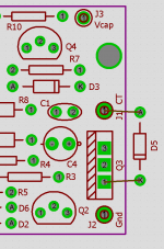
A zener could be added to the bottom of the board as shown here. A 12V 400mW is OK. Note that this view is from the top of the board, and the zener should be mounted on the bottom. Take care not to short the zener wires to other connections.
Edit: added to The HV Delay | Linear Audio NL
Thanks guys!
Jan
Edit: added to The HV Delay | Linear Audio NL
Thanks guys!
Jan
Attachments
Last edited:
Congratulations, Jan! You've got a nice and tight implementation of a great concept. Special kudos for (a) finding such a low cost, 1 kilovolt rated (!), depletion MOSFET; and (b) daring to use a microcontroller in pure analog circuitry. You could remind naysayers that Acoustic Research's virtual VU meters ("GhostMeter"TM) also employ microcontroller ICs...
_
_
Attachments

Rubli has made an even simpler delay, splice the B+ and mount the device here. No ground connection needed, no power supply needed.
Se http://n.manet.nu/tubedoc/rubli-article.pdf
Se http://n.manet.nu/tubedoc/rubli-article.pdf
Worth noting that delay applies a step B+ connection to output stage, doesn't aim to limit first filter cap peak voltage or reduce inrush.Rubli has made an even simpler delay
I'd say the relay shorts out the charge limiter once the cap is full, but this does not do so...
good point, but since there is low consuption on my headamp, i do not need it.
on those fets there is only 1-2v across d-s ; they are cold.
Physics does not support a delayed switch on. The potential between plate and cathode would need to be several thousand volts to rip electrons from the cathode and also consider the electrolytics. THere is ample literature on the subject if one goes hunting.
you are actually right.
some rectifiers have a long time to fully heat the cathode, literally working as softstart.

delay is required only for gas tubes, but softstart is what saves components.
Last edited:
- Home
- Amplifiers
- Tubes / Valves
- Tube amp high-voltage delay