Some of you might remember my article in AudioXpress of a few years ago for a tube amp high voltage delay. Many people build it, but it was time for a New & Improved version (really!).
AudioXpress published it and agreed to allow free download for diyaudio members (nice people there!).
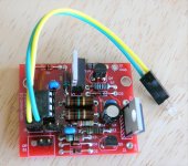
Jason agreed to make a kit available in the diyaudio store.
Let me know what you think and we can disuss details of the design here.
Jan
AudioXpress published it and agreed to allow free download for diyaudio members (nice people there!).
Jason agreed to make a kit available in the diyaudio store.
Let me know what you think and we can disuss details of the design here.
Jan

Well, you asked for itLet me know what you think and we can disuss details of the design here.

Mona
Attachments
Like that it's more easy to see the changes.What? You can use a red pencil?
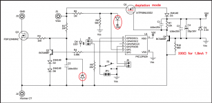
Yes.The depletion mode FET should have a different symbol?
A zener for safety, if the fet fails and replaced by another one without internal zenerWhat do you mean by the other red stuff?

The devider R8-R9 can produce a voltage much higher then Vd, no good for the PIC.
With R10=680Ω the current is limited to less then 1mA.In your article you stated 1,8mA. Still rather low for PIC+Q2drive+LED+zener
Mona
Last edited:
Yes. A zener for safety, if the fet fails and replaced by another one without internal zener
As you noticed, the FET has an internal zener. But yes, if you want to replace it with one without a build-in zener, it is a good idea to add one.
The divider R8-R9 can produce a voltage much higher then Vd, no good for the PIC.
The PIC has internal clamp diodes.
With R10=680Ω the current is limited to less then 1mA. In your article you stated 1,8mA. Still rather low for PIC+Q2drive+LED+zener
Mona
Part of that 1.8mA does not flow through R10. R10 is only there to assure some minimal headroom. The kit has a LED specifically selected for low current-high brightness, as described in the article.
The whole idea of this is to have a reliable delay switch that can be retro-fitted to pretty much any tube amp, without upsetting the supply and grounding, that uses minimal current and doesn´t need heatsinking.
Also maximum flexibility to set the delay from 20 secs to 254 secs in a simple way.
Jan
Last edited:
Member
Joined 2009
Paid Member
I keep reading that a delay in the high-voltage supply for a tube amp is unnecessary and can even be counterproductive if not well implemented, so is there generally not a consensus, it’s every body decides for them selves ? The article says the jury is out but my perception is at least on this form the people with a solid understanding of the science say it is not required. My post is probably taking this thread off in the wrong direction but I’m about to consider building a high voltage 845 amp I keep my eye out for important topics like this
Last edited:
I looked it up, you are right, clamp current 20mA no problem.The PIC has internal clamp diodes.
More comfortable the the old Cmos and TTL-logic, one had to be carefull not to activate the parasitic PNP transistor.
Yes, i see now, only the current for the PIC and zener.Part of that 1.8mA does not flow through R10. R10 is only there to assure some minimal headroom.
That's also the reason for D2 AND D6 !
Mona
Exactly!
I really thought a lot about keeping the current consumption low.
The earlier unit used a separate heater winding that had to be floating which meant often a separate small transformer. That's a nuisance.
But supplying it from the HV means it must be mean and lean ;-)
Even at 600V, 1.8mA is just over one watt, which is manageable.
Jan
I keep reading that a delay in the high-voltage supply for a tube amp is unnecessary and can even be counterproductive if not well implemented, so is there generally not a consensus, it’s every body decides for them selves ? The article says the jury is out but my perception is at least on this form the people with a solid understanding of the science say it is not required. My post is probably taking this thread off in the wrong direction but I’m about to consider building a high voltage 845 amp I keep my eye out for important topics like this
It depends on who you read, but there are people that feel it is absolutely necessary to extend tube life. The other thing is that at start-up, when no current is drawn, the HV can rise quite a lot higher than the operating design value. A 420V supply with 450V caps can easily go over 450V at no-load. That is also avoided with this unit.
I have also noticed is that it often prevents a switch-on thump because of the gentle HV rise.
Jan
There is another problem with delayed HT.
If the tubes are hot and autobias with fat chemicals on the cathode there is suddenly HT and -Vg=0 resulting in a big current surge in the finals.
Same thing with autobias circuits, no current sensed gives -V to the tubes turned down.
During the time to adjust the -V bias (can be very slow) to much current.Unless provisions are made to keep -V at it's max without HT.
Mona
I’m about to consider building a high voltage 845 amp I keep my eye out for important topics like this
What voltage/current will you need for the supply?
Jan
Member
Joined 2009
Paid Member
What voltage/current will you need for the supply?
Jan
I'm looking at a single channel mono set up, single ended. I have some 1kV capacitors that if used would dictate a B+ just under 1kV (paper in oil caps).
Current would have to be enough for the 845, driver and input/gain tube - possibly 150mA.
Tubes will all be cathode bias.
Funny. When I need an HV delay I just use one of these!
NE555 DC 12V Delay Relay shield Timer Switch Adjustable Module 0 To 10 Second | eBay
But I don't need to switch more than 400V, and I use this to control another relay with better ratings.
NE555 DC 12V Delay Relay shield Timer Switch Adjustable Module 0 To 10 Second | eBay
But I don't need to switch more than 400V, and I use this to control another relay with better ratings.
I'm looking at a single channel mono set up, single ended. I have some 1kV capacitors that if used would dictate a B+ just under 1kV (paper in oil caps).
Current would have to be enough for the 845, driver and input/gain tube - possibly 150mA.
Tubes will all be cathode bias.
Just finished a regulated supply that could handle that. Maybe something for another thread ;-)
Jan
Funny. When I need an HV delay I just use one of these!
NE555 DC 12V Delay Relay shield Timer Switch Adjustable Module 0 To 10 Second | eBay
But I don't need to switch more than 400V, and I use this to control another relay with better ratings.
You just need to change a few parts to get over 10 seconds. But at under 2 bucks that's ok. The 555 is reliable proven for many years.
Interesting thoughts !There is another problem with delayed HT.
If the tubes are hot and autobias with fat chemicals on the cathode there is suddenly HT and -Vg=0 resulting in a big current surge in the finals.
Same thing with autobias circuits, no current sensed gives -V to the tubes turned down.
During the time to adjust the -V bias (can be very slow) to much current.Unless provisions are made to keep -V at it's max without HT.
Mona
As for delayed B+, maybe it should be restored gradually, ramping up after 30s 50V/s or so. It could be done with a power FET, it will get hot but only for a limited time, reducing heatsink capacity. This does not cure the "autobias problem" though...
Interesting thoughts !
As for delayed B+, maybe it should be restored gradually, ramping up after 30s 50V/s or so. It could be done with a power FET, it will get hot but only for a limited time, reducing heatsink capacity. This does not cure the "autobias problem" though...
I've been thinking about a PIC to perform these functions but never built it. That's for the next version, else Jan gets bored
I just use two switches in my 833C amp. One turns on the 10V, 10A 833C filament supply, 6E5P plate supply and 833C bias supply, the second turns on the 2.3kV plate voltage for the 833C (with a soft start circuit). I throw the first switch, go get an appropriate beverage, then I throw the second switch.
Been working just fine for 5 years now. Still the original 833C tubes with very little sign of degradation.
Been working just fine for 5 years now. Still the original 833C tubes with very little sign of degradation.
Last edited:
- Home
- Amplifiers
- Tubes / Valves
- Tube amp high-voltage delay