Hi, LC could adapte the TSSA HP for +/-50Vdc? It would be really nice from you.
For fun il will try the liitle pcb for TSSA TT.
Marc
Testing/ironing out TSSA BIGBT, allowing/confirming a range of PSUS 45V-70V and issuing a board would be a happy practical conclusion of the Andrej ideas threads. What is the projected power range for those supply voltages?
TSSA BIGBT HP is high precision CCS driven-defined (1,72 mA source/sink) so all idle conditions depends on this value. Change of the supply potential would be peace of cake stuff, demands only to change the resistance value of the voltage dumping resistors (4 x 56 k, 4 x 22 k). All other parts would stay unchanged if they fulfill minimal potential margins. 😉
So we can produce one amp covering supply DC voltages (rails) from +/- 24-75 V with two pairs of outputs. Power calculations can be done for rehearsal by anyone himself. 😎
P.S. Values of 56 k are wrong, I made calculations with 1,172 mA instead 1,72 in a hurry. So the values will be corrected in a package when we will get few other improvements as well. This version is opened to be polished to high gloss ... 🙂
Last edited:
Thanks for explanation, the question was beacause i have a couple of 2x300va 2x25vac and 22.000µ/40v caps, so i will probably etch next week the pcb i posted and test with +/-25Vdc rail. I can also swap 3281/1302 TT to 4281/4302 TT to have more marge-in.
Marc
Marc
TSSA BIGBT HP is high precision CCS driven-defined (1,72 mA source/sink) so all idle conditions depends on this value. Change of the supply potential would be peace of cake stuff, demands only to change the resistance value of the voltage dumping resistors (4 x 56 k, 4 x 22 k). All other parts would stay unchanged if they fulfill minimal potential margins. 😉
So we can produce one amp covering supply DC voltages (rails) from +/- 24-75 V with two pairs of outputs. Power calculations can be done for rehearsal by yourself. 😎
That's a good news, just the LT1034 seems to be a pity to find even no stock on digikey and no to mouser.
Marc
That's a good news, just the LT1034 seems to be a pity to find even no stock on digikey and no to mouser.
Marc
TL431 with REF and CATHODE pins connected together would do the job quite the same, only with a little higher noise floor and 50 ppm/°C instead 20 ppm/°C voltage vs. temperature drift at LT1034. 😎
Last edited:
So we can produce one amp covering supply DC voltages (rails) from +/- 24-75 V with two pairs of outputs. Power calculations can be done for rehearsal by anyone himself. 😎
Andrej, we don't have expertise about BIGBT or their bias here to calculate on a glance. So, confess it all.😀 30-150W @ 8 Ohm for that schema?
TL431 with REF and CATHODE pins connected together would do the job quite the same, only with a little higher noise floor and 50 ppm/°C instead 20 ppm/°C voltage vs. temperature drift at LT1034. 😎
That's a another good news...
A another seems me strange is the IR LED????
Marc
Last edited:
Andrej, we don't have expertise about BIGBT or their bias here to calculate on a glance. So, confess it all.😀 30-150W @ 8 Ohm for that schema?
When i read that i feel me suddly less alone...
Marc
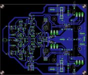
First try for TSSA_BIGBT_HP single layer. 165x135mm. TLP627 is not connected out for moment
Attachments
Last edited:
Just a little precision : BJT Bigbt transistors are mounted under pcb "sandwiched" between pcb and heatsink surface by the screw.
Marc
Marc
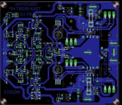
All day was rainy so i continue to play with eagle : consmetics changes and pcb reduction size was on programm
Attachments
Last edited:
Just a little precision : BJT Bigbt transistors are mounted under pcb "sandwiched" between pcb and heatsink surface by the screw.
Marc
Idefixes, you seriously grip the bull's saddle 😀
Very nice PCB indeed. 😉
Both IRF-s screaming to get in between the outputs, you see their tracks are way too looong. 🙄
Also the + and - outputs can be aligned with their pins. 😉
Look down, sch update, just at the right time hehe 😎

Idefixes, you seriously grip the bull's saddle 😀
Very nice PCB indeed. 😉
Both IRF-s screaming to get in between the outputs, you see their tracks are way too looong. 🙄
Also the + and - outputs can be aligned with their pins. 😉
Look down, sch update, just at the right time hehe 😎
I will take care all adwise. I tried with irf between BJT but not found solution in one layer...i will try again to integrate your advises.
Marc
next.......
LC, what are this "IR LED". I would be nice if you could communicated me the resistors value change for -/+50Vdc....i am not able to calculate them...
Thanks Marc
LC, what are this "IR LED". I would be nice if you could communicated me the resistors value change for -/+50Vdc....i am not able to calculate them...
Thanks Marc
Attachments
Last edited:
Member
Joined 2009
Paid Member
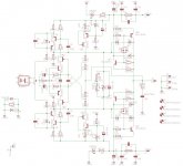
Here's an update with minor connection/parts changes, some values were recalculated.
jeez, this is supposed to be the Simplest ? 😱 I think this thread has lost the plot along the way. Pitty, I like really simple.
jeez, this is supposed to be the Simplest ? 😱 I think this thread has lost the plot along the way. Pitty, I like really simple.
Hi Bigun 😉
I can not manage more than two threads simultaneously, so logically one would be full of stuff. 😀
From simple to more complex version, all based on the same TSSA base core. It is the same like in school, gradually progressing the knowledge. 😎
Regards Andrej
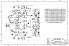
TSSA BIGBT HP different supply voltages - resistor values
Hi Marc 😉
Nice PCB improvement.
Attached schematic includes the table of calculated resistor values according to different supply voltages chosen. 😉
IR LED is infrared light emitting diode, high performance one compared to average LED-s. 😎
next.......
LC, what are this "IR LED". I would be nice if you could communicated me the resistors value change for -/+50Vdc....i am not able to calculate them...
Thanks Marc
Hi Marc 😉
Nice PCB improvement.
Attached schematic includes the table of calculated resistor values according to different supply voltages chosen. 😉
IR LED is infrared light emitting diode, high performance one compared to average LED-s. 😎
Attachments
Last edited:
Hi Marc 😉
Nice PCB improvement.
Attached schematic includes the table of calculated resistor values according to different supply voltages choosen. 😉
IR LED is infrared light emitting diode, high performance one compared to average LED-s. 😎
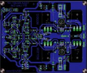
Youpi..that couldn't be better....I continue to work on pcb with some more components alignement and some mistake (0.22r 5W package) corrections.
On my version i put in the possibility to bypass the TLP627 since you have your own systeme to drive this unit -power management unit...if i remember-
Marc
IR LED is infrared light emitting diode, high performance one compared to average LED-s. 😎
Something like this : Product Folder - QED123 - Plastic Infrared Light Emitting Diode, Fairchild Semiconductor?
Marc
Mostly any 5 mm IR LED is okay. 😎
At current If=3,5 mA, forward IR LED voltage is app. 1,2 V and that is too low for proper cascode, so please provide two of them in series on the PCB. That will provide Vce=1,8V for VAS BC transistor. 😉
P.S. 2SA/2SC transistors needs on PCB 5-10°K/W heatsink, since they dissipate app. 0,7 W each at 75 V supply voltage. 😉
Last edited:
- Home
- Amplifiers
- Solid State
- TSSA - The Simplest Symmetrical Amplifier